Introduction
An excerpt from OmniGlot.com about the origin of Morse Code:
Morse Code was invented by Samuel F. B. Morse (1791-1872), a painter and founder of the National Academy of Design. He conceived the basic idea of an electromagnetic telegraph in 1832, and produced the first working telegraph set in 1836. This made transmission possible over any distance. The first Morse Code message, “What hath God wrought?”, was sent from Washington to Baltimore.
Today experienced operators copy received text without the need to write as they receive, and when transmitting, can easily converse at 20 to 30 words per minute. Morse Code will always remain a viable means of providing highly reliable communications during difficult communications conditions.
Morse Code can be transmitted using sound or light, as sometimes happens between ships at sea. It is used in emergencies to transmit distress signals when no other form of communication is available. The standard international distress signal is dot-dot-dot dash-dash-dash dot-dot-dot (SOS)
Description
This lab will use an LED to transmit the International Morse Code Distress Signal (S.O.S.). Here is what Morse Code looks like:
Parts Required
You will need the following to complete this Lab:
One Arduino Development Board (Duemilanove, Uno or Mega)
- One USB cable that has connectors matching your Arduino board and your computer
- One LED (any color)
- One Resistor (220 to 270 Ohms)
Programming
The letters S.O.S. would be transmitted as three dots, then three dashes, then three dots. This is sometimes written in text as “dit-dit-dit, pause, dah-dah-dah, pause, dit-dit-dit” where dit represents dots or short transmissions and dah represents dashes or longer transmissions.
To help students see some of the different programming possibilities, this code will be shown in three versions or variations:
- The “Bare-Bones” version. This version will be about as short and simple as this code can get.
- The “With Comments” version. The same as “Bare-Bones” with many comments to explain what is happening, and
- The “Subroutine” version, where code for the dots and dashes is in a subroutine.
All three programs will perform exactly the same. The third version will illustrate the use of several programming constructs that are common for more experienced programmers.
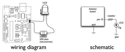
Hookup
Here is the wiring diagram and schematic. Pin 13 is used on the Arduino because pin 13 is also hard-wired to the on-board LED on the development board. It is a small surface-mounted LED marked “L” and placed near pin 13.
The Bare-Bones Program
void setup()
{
pinMode(13, OUTPUT);
}
void loop()
{
for (int x = 1; x <= 3; x++)
{
digitalWrite(13, HIGH);
delay(150);
digitalWrite(13, LOW);
delay(100);
} delay(100);
for (int x = 1; x <= 3; x++)
{
digitalWrite(13, HIGH);
delay(450);
digitalWrite(13, LOW);
delay(100);
}
delay(100);
for (int x = 1; x <= 3; x++)
{digitalWrite(13, HIGH);
delay(150);
digitalWrite(13, LOW);
delay(100);}
delay(2000)}
Bare-Bones with Comments
At this point, you could enter the program above, or cut and paste it from here into your IDE, and you would have a working program. Now, let’s take the same code and add comments so you can see what is going on:
For more detail: Arduino Lab 2 – Morse Code Generator