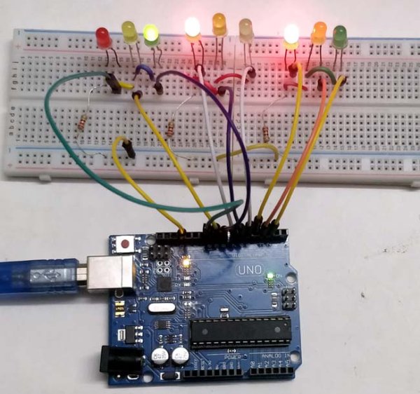
We all know about Arduino. It is one of the most popular open source micro controller board which is highly useful for doing DIY projects. This Arduino based 3-Way Traffic Light Controller is a simple Arduino DIY project which is useful to understand the working of traffic lights which we see around us. We have covered a more simpler version of traffic lights in this traffic light circuit. Here have demonstrated it for 3 sides or ways. Now let’s get into the project…
Components Required:
- 3*Red LED Lights
- 3*Green LED Lights
- 3*Yellow LED Lights
- 3*220ohm Resistors
- Breadboard
- Male To Male Connectors
- Arduino Uno With Ide Cable
Circuit Explanation:
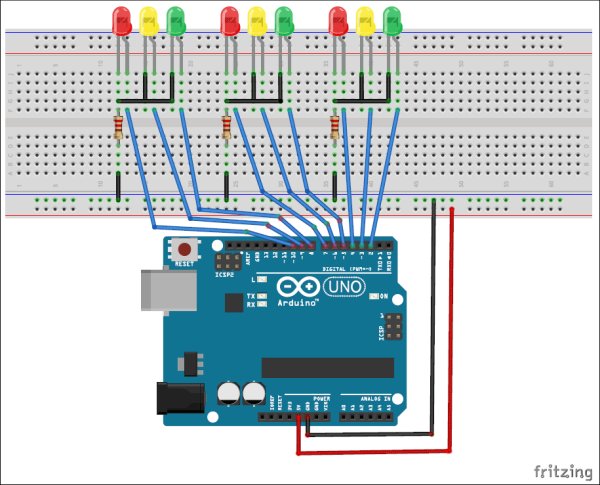
The circuit Diagram for Arduino Traffic Light Controller project is given below:
It’s pretty simple and can be easily built on bread board as explained in below steps:
- Connect the LEDs in the order as Red, Green, and Yellow in the breadboard.
- Place the negative terminal of the LEDs in common and connect the 220ohm resistor in series.
- Connect the connector wires accordingly.
- Connect the other end of the wire to the Arduino Uno in the consecutive pins(2,3,4…10)
- Power up the breadboard using the Arduino 5v and GND pin.
Program and Working Explanation:
The code for this Arduino Traffic Light Controller Project is simple and can be easily understood. Here we have demonstrated Traffic lights for the 3 ways road and the code glows LED’s on all the three sides in a particular sequence, in which the actual Traffic Lights works. Like, at a time, there will be two Red signals on any of the two sides and one Green light on the remaining side. And yellow light will also glow, for 1 second each time, in between transition from Red to Green, means first red light glows for 5 second then yellow light glows for 1 second and then finally green light will be turned on.
In the program, first we have declared pins (2,3…10) as output in void setup() for 9 LEDs (three on each side i.e. forward, right and left side).
   void setup() {
  // configure the output pins
  pinMode(2,OUTPUT);
  pinMode(3,OUTPUT);
  pinMode(4,OUTPUT);
  pinMode(5,OUTPUT);
  pinMode(6,OUTPUT);
  pinMode(7,OUTPUT);
  pinMode(8,OUTPUT);
  pinMode(9,OUTPUT);
  pinMode(10,OUTPUT);
}
Then in void loop() function we have written the code for traffic lights to be turned on and off in sequence as mentioned above.
void loop()
{

  digitalWrite(2,1); //enables the 1st set of signals
  digitalWrite(7,1);
  digitalWrite(10,1);
  digitalWrite(4,0);
  digitalWrite(3,0);
  digitalWrite(6,0);
  digitalWrite(8,0);
  digitalWrite(9,0);
  digitalWrite(5,0);
  delay(5000);
  ..... ....
  ..... ....
This process is well demonstrated in the Video Below. First the upside/forward side is opened (green), while the other two sides (i.e. left side and right side) remains closed with Red signal, with a delay of 5 seconds. Then the yellow light gets turned on at the right side for 1sec followed by the Green light, leaving other two sides (i.e. upside and left side is red) closed with Red Light and 5seconds delay. Then yellow on the left side glows for 1sec followed by green one, leaving upside and right side Red with 5sec delay. This process is looped in void loop() function for continuous process. Here we can modify delays for which the Red, yellow and Green light remain on and off.
The complete Arduino code and Video for this Arduino Traffic Light Project is given below.
Code
Video
Source: Arduino Based 3-Way Traffic Light Controller