DAC is short for Digital to Analog Converter. In this article we play around the code Michael Smith created for a PWM based DAC. I modified his code so that other DAC options could be tried. I compare the 8-Bit PWM DAC with the R2R DAC at various numbers of bits. You might be surprised at how well a 4-bit DAC sounds. This article includes several sound samples for the various DAC options and demonstrates some software abstraction that allows for multiple DAC options.
This article is part of the series on Arduino Sound Generation. I decided to drop the Part 1, 2, 3 distinction as much of the content is not dependent on the previous articles.
Related articles:
- Using PWM to do sound Link
- Using timer interrupts Link
- Playing a Melody Link
- Getting ready for sound projects Link
- Creating sound, what are the options? Link
Of all the various methods of sound generation the DAC method seems most versatile to me. As mentioned before DAC is a common short name for Digital to Analog Converter. Basically a binary/digital value is converted to an analog/voltage value. An 8-Bit DAC would convert a binary value in the range of 0 to 255 into an analog voltage from 0 to 5V. The exact voltage range of the conversion is dependent on the DAC configuration but for most things we will play with, 0 to 5V will work.
DAC Biasing for +/- swing
Since analog signals, especially sound, needs to swing plus and minus around 0V we often bias the DAC so that mid scale is considered 0V. If the DAC outputs from 0 to 5V then we usually bias the signals so that 2.5V is translated to 0V. If we generate our output signals so that half scale is 2.5V then we can AC couple the output to get a +/- 2.5V swing.
The half scale biasing may be a bit confusing but really it’s easy once you get the general idea. We just call 1/2 scale zero so that any numbers above 1/2 are positive and below are negative. For an 8 bit converter we can use the MSB as a sign bit to make this happen. Consider that decimal 128 is 10000000 in binary. Note that the MSB is set and this is basically half scale of the possible 0-255 range. Think of the MSB as a sign bit, it’s one for positive values and 0 or negative.
Using this 1/2 scale bias we can convert any digital number that might represent sound data into a value to load into a DAC. The first step is to convert the number into the range of +/-127 and add 128 to it. In this example that will make the analog version swing from 0 to 5V with the original zero point set at 2.5V. We can remove that 2.5V bias in the hardware with a simple series capacitor.
A/C Coupling
The series capacitor is not even needed in most applications. For example I use my sound card line input to do these experiments. This input has a series capacitor. The series capacitor is used to provide A/C coupling. This just means that the signal swings evenly around 0V. The +/- voltage swing is enforced about the average DC level by the capacitor. Of course there is a frequency response for the series capacitor but the value of the capacitor is usually high enough so that it will not be a problem for audio frequency ranges.
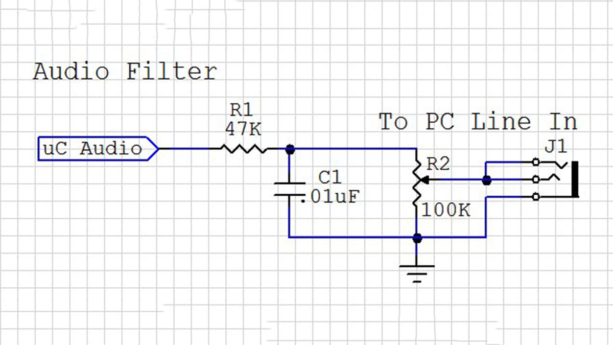
Filtering the DAC output
This diagram shows the circuit I used between the various DAC outputs and my PC sound card input. The series resistor and capacitor to ground form a simple filter to knock off the high frequency noise caused by the DAC switching instantly between the voltage values. It removes the high frequency components. The 100K variable resistor (POT) lets me adjust the output voltage level for each DAC. A line input should be kept in the 1V Peak to Peak range or +0.5 to -0.5 range. Since the sound card has A/C coupling I only need to adjust the amplitude using this POT as a voltage divider. Also note that I connected both the right and left side inputs to the filtered output.
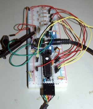
[box color=”#985D00″ bg=”#FFF8CB” font=”verdana” fontsize=”14 ” radius=”20 ” border=”#985D12″ float=”right” head=”Major Components in Project” headbg=”#FFEB70″ headcolor=”#985D00″]Arduino[/box]
For more detail: Arduino Audio DAC Options