[box color=”#985D00″ bg=”#FFF8CB” font=”verdana” fontsize=”14 ” radius=”20 ” border=”#985D12″ float=”right” head=”Major Components in Project” headbg=”#FFEB70″ headcolor=”#985D00″]
Ardu-Bot-Tom List of Materials
Controller Parts:
1x – Arduino Uno
1x – 9V Battery
1x – 433Mhz TX Module
1x – SparkFun Joystick
Robot Parts:
1x – Arduino Uno
2x – 9V Battery
1x – 433Mhz RX Module
1x – TB6612FNG Breakout Board
1x – Pololu 3 1/2” x 2” White Breadboard
1x – Pololu Universal Plate Set
1x – Tamiya Twin Motor Gearbox
2x – Pololu Off-Road Tires
Some Zip-Ties
Some Crazy Glue
Common Parts:
2x – Heat-Shrink Wrappers
1x – SparkFun Inventors Kit
1x – Double Sided Tape Roll
[/box]
Introduction
Ardu-Bot-Tom is a fun project created to show you how you can use wireless transmission modules to send commands to your robots, also it touches some specific subjects such as, servo interfacing and programming, joystick value mapping and the calculations required to determine which way the joystick is pushed, using the Serial Monitor to monitor and debug your robot’s sketch and interfacing and programming the Arduino with the TB6612FNG board. The main idea behind Ardu-Bot-Tom is to create a fun robotics platform which movements can be easily controlled and can be built upon to create a more complex robotic system. The robot is very fun to play with as well, you can make two and have a race, or add huge tires and make a monster truck. In other words, the possibilities are endless in what you can do with the Ardu-Bot-Tom platform. In order to achieve get it working, the project is broken down into four major parts described in the index bellow.
Project Index
Part 1: Controller Interfacing
a. Interfacing the Joystick (Command Generation)
b. Interfacing the TX module (Command Transmission)
Part 2: Programming and Testing the Controller
a. Reading, mapping and sending the joystick commands
b. Testing the controller with the serial monitor
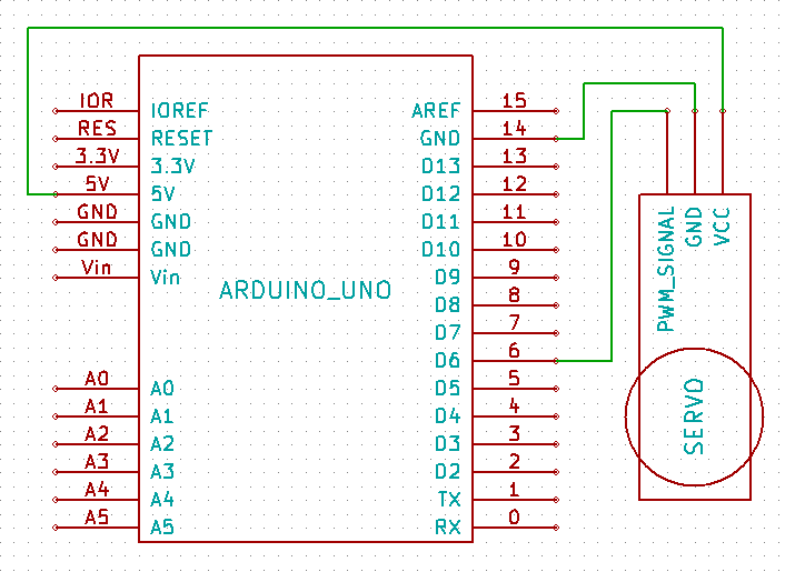
Part 3: Robot Interfacing
a. Interfacing the RX module (Command Reception)
b. Interfacing the Servo (Left and Right)
c. Interfacing the TB6612FNG dual motor driver (Forward and Backwards)
Robot Programming And Testing
a. Receiving and realizing the commands
b. Programming the servo movement
c. Programming the motor driver movement
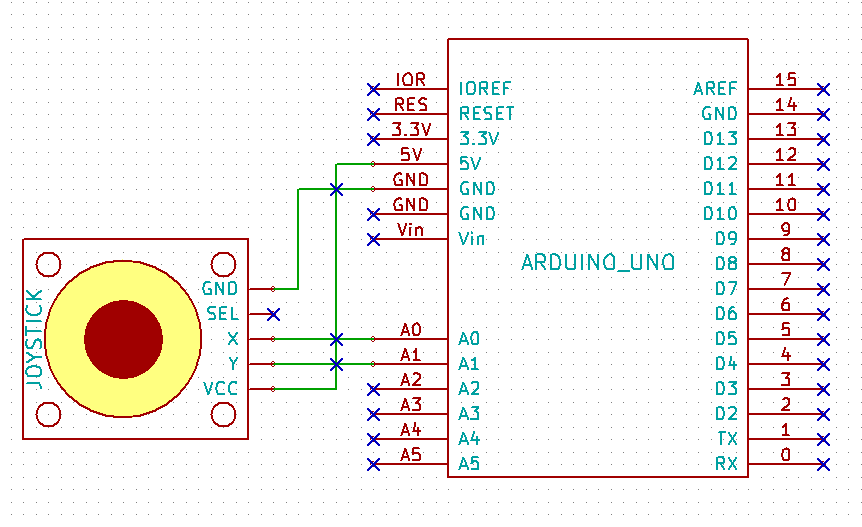
Part 1. Controller Interfacing
1a. Interfacing the Joystick
Since we are using an analog joystick for this application, the physical interface is pretty straight forward. You will connect the pins as follows:
1b. Interfacing the TX Module
The TX module is very simple as well. Connect it to the Arduino as follows:
Part 2: Programming and Testing the Controller
2a. Reading, Mapping and Sending the Joystick Commands
For those that did not know, the analog joystick consists of a momentary pushbutton and two potentiometers. One represents the X axis and the other one represents the Y axis. By connecting each of the potentiometers to two of our analog pins on the Arduino, and reading in the changes produced by the changing resistance on the pin due to any movement, we can calculate what direction the joystick was pushed towards.
The process is as follows:
- When the microcontroller starts up, the setup() function is executed first, here we must read and store the two initial “zero” values for each axis.
- After the setup() function executes, the Arduino will enter an infinite loop() function where we must constantly poll the updated values of the two axis and compare them to the initial “zero” values.
- We must create 4 variables that will store 4 distance values. The first one is how far is the joystick pushed left from the “zero” point, the second how far right, third up and then down.
- We then compare all 4 and find the largest, and that will give us what command we must send to the robot.
- Finally we do a Serial.write(‘X’) where X is the command character we want to send.
Note: The command characters are F = Forward, B = Backwards, L = Left and R = Right.
The Controllers Sketch
//Define the input pins for the joystick and the variables to keep track of its state
int vertical = A0,horizontal = A1,vVal,hVal,vZero,hZero;
void setup()
{//Here we set up everyting....
  Serial.begin(4800);
  //Set the initial "zero" vertical position value of the joystick
  vZero = map(analogRead(vertical),0,1023,0,255);
  //Set the initial "zero" horizontal position value of the joystick
  hZero = map(analogRead(horizontal),0,1023,0,255);
}
void loop()
{ //This will happen over and over and over and over again......
  //Read the vertical pot value
  vVal = map(analogRead(vertical),0,1023,0,255);
  //Read the horizontal pot value
  hVal = map(analogRead(horizontal),0,1023,0,255);
  //Declare variables to store the cardinal distances from the "zero" point
  //and an offset point to activate a direction
  int FVal = 0,BVal = 0,RVal = 0,LVal = 0,centerOffset = 15;
  //Find the distance from the ("zero" position value +/- the offset value)
  //for forward and backwards
  //If the joystick is pushed up passed the "zero" point + the offset value
  if(vVal > (vZero + centerOffset))
  {
    //store the distance up from the "zero" point
    FVal = vVal - vZero;
    //clear any previous distance from the bottom side
    BVal = 0;
  }
  //If the joystick is pushed down passed the "zero" point - the offset value
  else if(vVal < (vZero - centerOffset))
  {
    //store the distance down from the "zero" point
    BVal = vZero - vVal;
    //clear any previous distance from the top side
    FVal = 0;
  }
  //Find the distances from the ("zero" position value +/- the offset value)
  //for left and right
  //If the joystick is pushed left passed the "zero" point + the offset value
  if(hVal > (hZero + centerOffset))
  {
    //store the distance left from the "zero" point
    LVal = hVal - hZero;
    //clear any previous distance from the right side
    RVal = 0;
  }
  //If the joystick is pushed right passed the "zero" point - the offset value
  else if(hVal < (hZero - centerOffset))
  {
    //store the distance right from the "zero" point
    RVal = hZero - hVal;
    //clear any previous distance from the left side
    LVal = 0;
  }
  //Find the largest of the four and that's the direction we are going
  //If the joystick is pushed furthest forward
  if(FVal > BVal && FVal > RVal && FVal > LVal)
  {
    //then send 'F' through usart
    Serial.write('F');
    //Show what happened in the serial monitor
    Serial.println("Controller: Moving Forward");
  }
  //If the joystick is pushed furthest backwards
  else if(BVal > FVal && BVal > LVal && BVal > RVal)
  {
    //then send 'B' through usart
    Serial.write('B');
    //Show what happened in the serial monitor
    Serial.println("Controller: Moving Backwards");
  }
  //If the joystick is pushed furthest left
  else if(LVal > RVal && LVal > FVal && LVal > BVal)
  {
    //then send 'L' through usart
    Serial.write('L');
    //Show what happened in the serial monitor
    Serial.println("Controller: Moving Left");
  }
  //If the joystick is pushed furthest right
  else if(RVal > LVal && RVal > FVal && RVal > BVal)
  {
    //then send 'R' through usart
    Serial.write('R');
    //Show what happened in the serial monitor
    Serial.println("Controller: Moving Right");
  }
  else
  {
    //The character U keeps continuous 0's and 1's on the serial line which
    Serial.write('U');
    //helps with synchronization at the receiver side
    Serial.println("Controller: Not Moving");
  }
}
2b. Testing the Controller with the Serial Monitor
Once you have loaded the code onto the Arduino, we must check to make sure that the commands are being sent correctly. To do this, we can use the Serial Monitor dialog that is located inside the Arduino IDE. To open it you can use the shortcut [Ctrl+Shift+M] or you can navigate to Tools / Serial Monitor.
For more detail: Ardu-Bot-Tom – RF Link Controlled Robot