This example shows you how to read an analog input on Pin 0, convert the values from analogRead() into voltage, and print it out to the serial monitor.
Circuit:
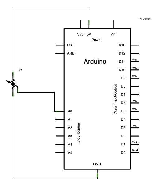
image developed using Fritzing. For more circuit examples, see the Fritzing project page
Connect the three wires from the potentiometer to your Arduino board. The first goes to ground from one of the outer pins of the potentiometer. The second goes from 5 volts to the other outer pin of the potentiometer. The third goes from analog input 2 to the middle pin of the potentiometer.
By turning the shaft of the potentiometer, you change the amount of resistance on either side of the wiper which is connected to the center pin of the potentiometer. This changes the voltage at the center pin. When the resistance between the center and the side connected to 5 volts is close to zero (and the resistance on the other side is close to 10 kilohms), the voltage at the center pin nears 5 volts. When the resistances are reversed, the voltage at the center pin nears 0 volts, or ground. This voltage is the analog voltage that you’re reading as an input.
The Arduino has a circuit inside called an analog-to-digital converter that reads this changing voltage and converts it to a number between 0 and 1023. When the shaft is turned all the way in one direction, there are 0 volts going to the pin, and the input value is 0. When the shaft is turned all the way in the opposite direction, there are 5 volts going to the pin and the input value is 1023. In between, analogRead() returns a number between 0 and 1023 that is proportional to the amount of voltage being applied to the pin.
Schematic:
Code:
In the program below, the very first thing that you do will in the setup function is to begin serial communications, at 9600 bits of data per second, between your Arduino and your computer with the line:
Serial.begin(9600);
[box color=”#985D00″ bg=”#FFF8CB” font=”verdana” fontsize=”14 ” radius=”20 ” border=”#985D12″ float=”right” head=”Major Components in Project” headbg=”#FFEB70″ headcolor=”#985D00″]
Hardware Required
- Arduino Board
- a variable resistor, like a potentiometer
[/box]
For more detail: Analog Read Voltage using Arduino