This is the project that got Autodesk’s CEO Carl Bass a little extra attention from the TSA on his way to MakerFaire Tokyo. Here’s an article about that…
We made this as way to demo a few things you can do with our apps, 123D Circuits and 123D Design : Design circuits. Simulate the circuits online. 3D Model online and prepare for 3D Printing.
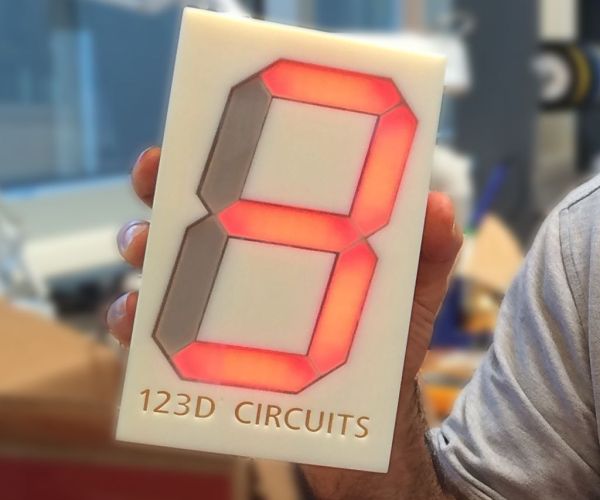
Here’s how it works – pick up the die, shake it, watch while the numbers change until it stops on a number between 1 and 6. It’s that simple… It’s just like a real die except it’s huge and has circuitry and a 3D printed enclosure. So I’ll admit – it’s a little more involved than a tiny plastic die, but it’s way cooler.
But don’t take my word for it – You can make one too, the files are online. Keep reading for the links.
Step 1: The Online simulation
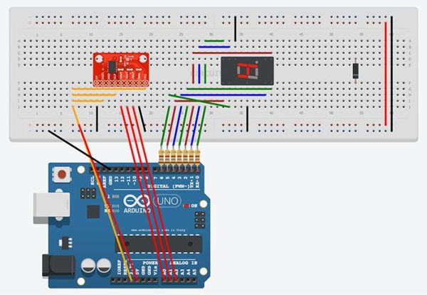
You should see an embedded viewer of the virtual breadboard from the 123D Circuit project. It should look similar to the image above.
If you need help we have this getting started instructable.
Once you’re in the viewer you can scroll around and zoom in and out. If you want to start the simulation or make changes you first need to make this circuit your own. Click this link to open the Accelerometer Dice circuit in the 123D Citcuits editor. Once you’re in press “Fork” to make a copy for you to have fun with. Don’t worry about screwing it up when you add your own stuff, our original will remain unchanged.
Step 2: More Power, Scotty!
The breadboard view from the previous step is a nice simulation of the die and you can learn a lot from it – but to build this circuit using the larger 7-segment display we’re going to need a slightly different design to accommodate its need for a lotmore power, Scotty.
The next steps dig deeper into that design…
The really large 7-segment display draws a lot more current than an Arduino can provide per pin and drops upwards of 12.4 volts so the whole circuit needs a more capable power supply and uses discrete transistors to stop and start the flow of current through the segments. The Arduino is still there, it’s just acting more like the brain than the brawn. We’re using two 9 volt batteries in series, the 18 volts gives us some headroom and ensures that as the batteries drain over time the die will shine bright for a a while. For those interested – here’s a link to the large 7-segment datasheet.
Step 3: Parts List
Here is what’ on the inside and what you’ll need. There are three pictures on this step.
Bill Of Materials (BOM)
1 Arduino UNO (could be any Arduino that takes a standard shield)
1 circuit board designed in 123D Circuits (http://123d.circuits.io/circuits/48798/)
1 triple axis accelerometer breakout – MMA7361 from Sparkfun
1 extra huge 6.5″ tall 7-segment display from Sparkfun
1 on/off switch (spst)
1 barrel connector for DC power – size “M”
batteries in series (you’ll want at least 14 volts, here we’re using 18 volts)
battery holders
wire
Parts list for the Arduino shield designed in 123D Circuits are here. Press “Fork” and all of a sudden the circuit is yours. I’ll cover this in more detail on the next step.
Tools
solder or soldering paste
soldering iron
multi meter
wire strippers
tweezers
computer with usb cable to program the Arduino
Optional
box or enclosure, we 3D printed one
double-sided sticky foam tape – to hold things together
screws, glue, or epoxy – to hold things inside the inclosure
Step 4: The Arduino Code
There are two slightly different code bases for this project because the breadboard version of the circuit requires slightly different code than the larger more powerful version. This is due to the the larger version working with a real accelerometer and the breadboard version working with a virtual accelerometer. BTW, to shake the virtual accelerometer just click on it.
1) The Arduino code for the breadboard version is in the 123D Circuits project, just single-click on the Arduino then click on “Arduino Code Editor”
2) The Arduino code for the larger more powerful version is on this page – scroll down.
Here’s a link to the accelerometer’s library. https://code.google.com/p/mma7361-library/
#include <AcceleroMMA7361.h> //should be in Documents/Arduino/Libraries (on a Mac)
//download it here https://code.google.com/p/mma7361-library/

//mapping of the Arduino board to the large 7-segment from Sparkfun, letter is segment, number is Aruino Digital Output
// https://www.sparkfun.com/products/8530
//    a
// f      b
//    g
// e      c
//    d

int a = 0;
int b = 6;
int c = 5;
int d = 4;
int e = 3;
int f = 1;
int g = 2;

//mapping of the accelerometer board from sparkfun, these are Arduino outputs
// https://www.sparkfun.com/products/9652

int st = 8;     //self test (output from Arduino)
int gsel = 9;   //g-force range, +-1.5g and +-6g  (output from Arduino)
int zg = 10;    //zero g (input to Arduino)
int slp = 11;   //sleep (output from Arduino)

AcceleroMMA7361 accelero;   //create the accelero object

// the setup routine runs once when you press reset button on Arduino or power up:
void setup() {

  // initialize the digital pin as an output.
  pinMode(a, OUTPUT);
  pinMode(b, OUTPUT);
  pinMode(c, OUTPUT);
  pinMode(d, OUTPUT);
  pinMode(e, OUTPUT);
  pinMode(f, OUTPUT);
  pinMode(g, OUTPUT);

  writeDigit(-1);    // turn off all segments

  // Serial.begin(9600);          //uncomment this line for debugging, it will otherwise mess with the numbers!
  accelero.begin(slp, st, zg, gsel, A0, A1, A2);  //config the accelero to use the pins from above and to read analog values from A0, A1, A2
  accelero.setARefVoltage(5);                     //telling accelero that the AREF voltage is 5V  (to get higher resolution you'd set this to 3.3 and blue-wire it on the board)
  accelero.setSensitivity(LOW);                   //sets the sensitivity to +-1.5G
  accelero.calibrate();                           //you  need to do this for brake light, probably not for dice.

}

void writeDigit(int digit) {  //calling this function sets the segments to look like an intiger 0-9, we never show 0, or 9.  -1 is all off.
  Serial.print("digit: ");
  Serial.print(digit);
  Serial.print("\n");

  switch(digit) {
    case 0:
      digitalWrite(a, HIGH);
      digitalWrite(b, HIGH);
      digitalWrite(c, HIGH);
      digitalWrite(d, HIGH);
      digitalWrite(e, HIGH);
      digitalWrite(f, HIGH);
      digitalWrite(g, LOW);
      break;
    case 1:
      digitalWrite(a, LOW);
      digitalWrite(b, HIGH);
      digitalWrite(c, HIGH);
      digitalWrite(d, LOW);
      digitalWrite(e, LOW);
      digitalWrite(f, LOW);
      digitalWrite(g, LOW);
      break;
    case 2:
      digitalWrite(a, HIGH);
      digitalWrite(b, HIGH);
      digitalWrite(c, LOW);
      digitalWrite(d, HIGH);
      digitalWrite(e, HIGH);
      digitalWrite(f, LOW);
      digitalWrite(g, HIGH);
      break;
    case 3:
      digitalWrite(a, HIGH);
      digitalWrite(b, HIGH);
      digitalWrite(c, HIGH);
      digitalWrite(d, HIGH);
      digitalWrite(e, LOW);
      digitalWrite(f, LOW);
      digitalWrite(g, HIGH);
      break;
    case 4:
      digitalWrite(a, LOW);
      digitalWrite(b, HIGH);
      digitalWrite(c, HIGH);
      digitalWrite(d, LOW);
      digitalWrite(e, LOW);
      digitalWrite(f, HIGH);
      digitalWrite(g, HIGH);
      break;
    case 5:
      digitalWrite(a, HIGH);
      digitalWrite(b, LOW);
      digitalWrite(c, HIGH);
      digitalWrite(d, HIGH);
      digitalWrite(e, LOW);
      digitalWrite(f, HIGH);
      digitalWrite(g, HIGH);
      break;
    case 6:
      digitalWrite(a, HIGH);
      digitalWrite(b, LOW);
      digitalWrite(c, HIGH);
      digitalWrite(d, HIGH);
      digitalWrite(e, HIGH);
      digitalWrite(f, HIGH);
      digitalWrite(g, HIGH);
      break;
    case 7:
      digitalWrite(a, HIGH);
      digitalWrite(b, HIGH);
      digitalWrite(c, HIGH);
      digitalWrite(d, LOW);
      digitalWrite(e, LOW);
      digitalWrite(f, LOW);
      digitalWrite(g, LOW);
      break;
    case 8:
      digitalWrite(a, HIGH);
      digitalWrite(b, HIGH);
      digitalWrite(c, HIGH);
      digitalWrite(d, HIGH);
      digitalWrite(e, HIGH);
      digitalWrite(f, HIGH);
      digitalWrite(g, HIGH);
      break;
    case 9:
      digitalWrite(a, HIGH);
      digitalWrite(b, HIGH);
      digitalWrite(c, HIGH);
      digitalWrite(d, HIGH);
      digitalWrite(e, LOW);
      digitalWrite(f, HIGH);
      digitalWrite(g, HIGH);
      break;
    case -1:
      digitalWrite(a, LOW);
      digitalWrite(b, LOW);
      digitalWrite(c, LOW);
      digitalWrite(d, LOW);
      digitalWrite(e, LOW);
      digitalWrite(f, LOW);
      digitalWrite(g, LOW);
      break;
  }
}

int get_g() {                        //gets the length of the g force vectors
  int x = accelero.getXAccel();
  int y = accelero.getYAccel();
  int z = accelero.getZAccel();

  int gf = abs(sqrt(x*x+y*y+z*z)-100);  // the "-100" is roughly subtracting out gravity

  if (gf > 50) {
    Serial.print("g: ");
    Serial.print(gf);
    Serial.print("\n");
  }

  return gf;
}

int digit = 0;
int count = 0;     // counter
int count2 = 0;    // another counter

int state = 0;
// 0 = idle
// 1 = shaking
// 2 = show_result

int sum = 0;
int cur = 0;
int res;

// the loop routine runs over and over again forever:
void loop() {
  cur = get_g();
  sum += cur;
  if (sum < 0) sum = 0;

  switch(state) {
    case 0:                      // idle state, if cur is >70 then go to state 1
      if (cur > 70) {
         state = 1;
         count = 0;
         count2 = 0;
      }
      break;
    case 1:                       // actively shaking,
      if (count2 == 10) {         // 10 is 100ms
        writeDigit(sum % 6 + 1);  // show a random number every 100ms. Sum is a random number depending on how long the code is running and how you shake the die.
        count2=0;
      } else {
        count2++;
      }
      if (cur > 55) {             // from here until the break it is checking how long it has been since shaking stopped, if over 250ms without seeing g>55 go to state 2
         state = 1;
         count = 0;
      } else {
        if (count > 25) {
          state = 2;
          count = 0;
        } else {
          count ++;
        }
      }
      break;
    case 2:                     // showing the result, the delay times are in ~ centi-seconds
      if (count == 0) writeDigit(sum % 6 + 1);
      if (count == 10) writeDigit(sum % 6 + 1);
      if (count == 25) writeDigit(sum % 6 + 1);
      if (count == 45) writeDigit(sum % 6 + 1);
      if (count == 70) writeDigit(sum % 6 + 1);
      if (count == 100) writeDigit(sum % 6 + 1);
      if (count == 135) {       // from here to close of {} it is showing the final result, slowing down as it goes
        res = sum % 6 + 1;
        writeDigit(res);
      }

      if (count == 185) writeDigit(-1);
      if (count == 235) writeDigit(res);
      if (count == 285) writeDigit(-1);
      if (count == 335) {
        writeDigit(res);
        state = 0;
        count = 0;
      }
      count++;
      break;
  }
  delay(10);

//uncomment out this small loop to test that all segments are working. (comment out the other "void loop" lines)
//void loop() {
//    writeDigit(8);
//  delay(10);
}

For more detail: Accelerometer Dice with 123D Circuits