After we came up with the Bi-color LED Matrix Driver Module kit, we have been looking around for interesting projects to work with it.
You may be interested in some of the projects we have put up at instructables using this LED Matrix kit.
- Instructable to build a Arduino (SPI) 7 Bi-color LED Matrix Scrolling Text Display
- Instructable to build a Arduino based Bi-color LED Matrix Tetris Game
Most electronics hobbyist seems to be interested in projects involving Audio Spectrum Analyzer/Visualizer at some point in time. We decided to come up with this instructable to show how an Audio Spectrum Visualizer can be built using the Bi-color LED Matrix DIY kits.
As usual, before we decided to come up with this instructable, we browsed through the existing instructables to check if there are any similar projects. There is already a handful of instructables involving Spectrum Analyzers/Visualizers but we decided to go ahead with this instructable as we will be offering something different here and hopefully someone may find it useful.
To build this project, basic electronics knowledge with electronics component soldering skill and some knowledge on using the Arduino are required.
You may view the following YouTube video to see what we are building.
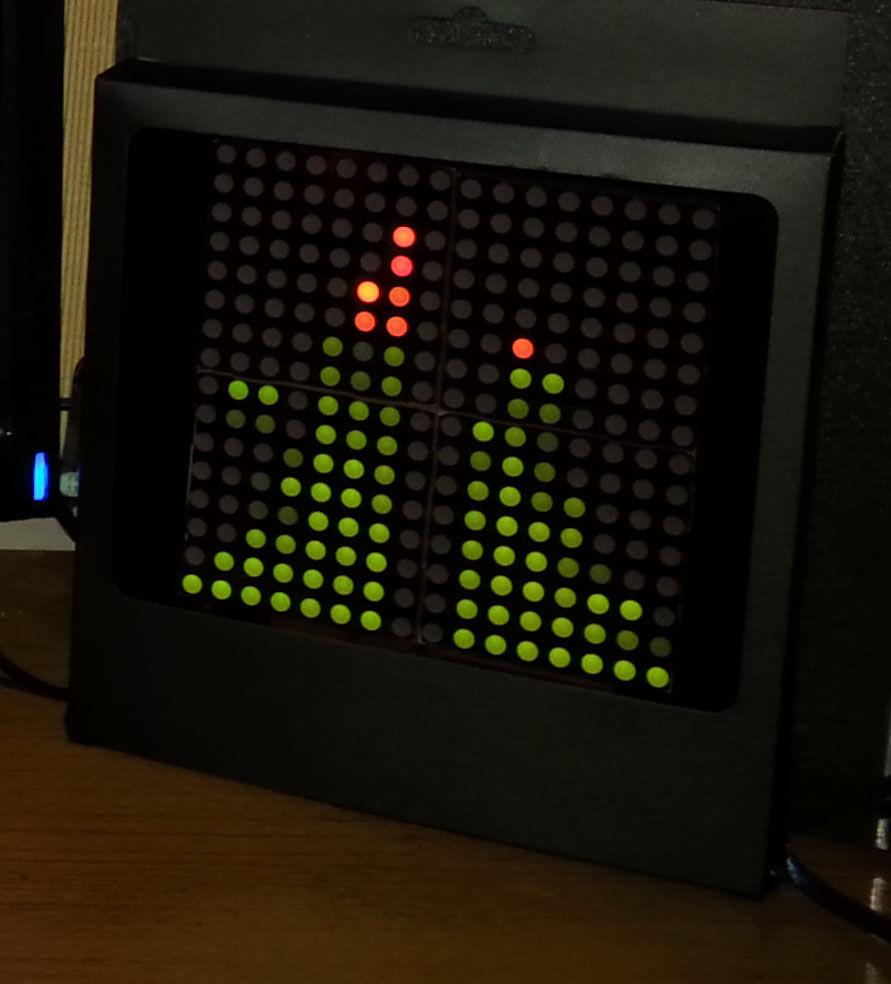
Step 1: Building the Arduino Bi-color LED Matrix Audio Spectrum Visualizer
We will be building a two LED Matrix tall stereo audio spectrum visualizer here driven by an Arduino Nano. We will basically be using four Bi-color (Red and Green) LED Matrix Driver Module kits from jolliFactory and two MSGEQ7 IC chips made by Mixed Signal Integration.
Two of the LED Matrix kits are for the audio left channel and another two for the audio right channel. Each of these modules uses two MAX7219 Display Driver ICs to drive a Bi-color LED Matrix. These ICs are excellent because they take a lot of work off the micro-controller and simplify the wiring and logic design.
You can find this Bi-color LED Matrix Driver Module kit from here.
This kit comes with all through-hole components and someone with basic soldering skill should be able to assemble it without much difficulty.
See the following YouTube video on how to assemble the LED Matrix Driver Module Kit:
The MSGEQ7 IC is a single channel seven band Graphic Equalizer Display Filter. By feeding an audio signal to it, it will filter out seven frequency bands centred around 63Hz, 160Hz, 400Hz, 1,000Hz, 2,500Hz, 6,250Hz, and 16,000Hz.
The seven frequencies are peak detected and multiplexed to the output to provide a DC representation of the amplitude of each band. All we need is to read these DC values with the microcontroller analog input and output the spectrum to the Bi-color LED Matrix displays.
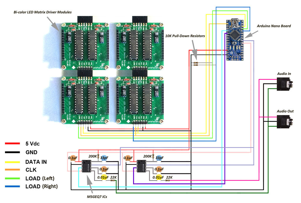
We need two MSGEQ7 ICs here, one for the left and another for the right audio channel. The wiring connection diagram above shows how a MSGEQ7 IC is typically connected.
Step 2: Wiring
After the four LED Matrix kits are completed, they are connected together with the two MSGEQ7 ICs and micro-controller as shown in the wiring diagrams. One of the wiring diagrams is with the LED Matrices removed for a better view of the connections. An Arduino Nano is used here to control the entire electronic circuit setup.
Note the use of 10Kohms pull-down resistors on the LOAD input pins for the LED Matrix modules. When power is first applied to the micro-controller or when they are reset, their I/O lines float. The LED Matrix module MAX7219 ICs can see this as valid data and display garbage until the micro-controller gains control. The pull-down resistors prevent these problems.
Except for the four Bi-color LED Matrix Driver modules, we hook up the entire circuit on a small piece of perf-board around 90mm x 30mm. See above for our completed circuit on perf-board.
Note there are two 3.5mm stereo audio jack sockets in the wiring diagram in the previous section. One serves as a stereo audio input and the other is a pass-through output which allows you to connect this Audio Spectrum Visualizer in-line between your audio source and your stereo system. However, due to space constraint on our perf-board, we are using a 4 pin angle header to replace one of the 3.5mm stereo audio jack sockets and we had to modify our audio cable for it to fit to the 4 pin angle header. If you are working on this project, a larger perf board around 110mm x 30mm should be sufficient to populate all the correct parts required for this project.
Step 3: Programming the Arduino Board
The Arduino board needs to be loaded with the Arduino sketch to drive the Audio Spectrum Visualizer.
We used Arduino IDE V1.03 for our project. Download the Arduino sketch below for this project and upload it into your Arduino board.
Download jollifactory_Audio_Spectrum_Visualizer_V1_0.ino
You may amend the sketch to enhance the visualizer to your liking. For us, we like the slow falling effect for each of the frequency band’s peak.
For more detail: Arduino based Bi-color LED Matrix Audio Spectrum Visualizer