Motivation:
Playing in a 2 piece band, with the drums and lots of other samples being played back as backing tracks, there was a need to use a looper to add in more elements to the tracks. A hardware based looper fails in this respect, since there is no way to maintain synchronisation. Meaning, slight discrepancies between triggering the start loop and end loop, even if it’s ever so minute, will add up as the bars progress, and since there’s no drummer to adapt to the loop, it will eventually run off time.
Thus, a software based looper is the way to go. Not just because you can maintain tempo based synchronisation on the DAW software that you’re hosting the plugin, but also because most of these software loopers are free, and more functional than a hardware looper could ever be.
There are quite a few to choose from:
Since your arms are occupied with the daunting task of playing an instrument, you need to control the parameters of the looper through your foot. This is where the midi foot controller comes in. If you aren’t familiar with what MIDI is, here an article.
Many midi controllers are available in the market, and the Beheringer FCB1010 is one of the most popular ones out there. But the perks of building you’re own are:
- Cost: you can build one for 1/8th the cost of a commercially available one.
- Customization: You can build a controller as per your requirement. This controller has the specs that I want, your needs maybe different. This instructable is thorough enough to act as a guide for a generic midi controller, rather than being confined and limited to someone else’s project.
- It’s USB bus powered, there is no need for an external power supply.
- And the perk which is often ignored the most, it’s fun ! You get to learn something new, and you’ll have something to show for your efforts by the end of it.
The concept is quite simple and straightforward. You press a button, the arduino interprets the signal arriving from the button as a midi “control change” signal (typically represented as MIDI CC), and this signal can be mapped to respond to any of the parameters of the looper.
Step 1: Getting started..
This project can be done using any micro-controller based on the arduino architecture. I chose a Teensy 3.1. The reason for this has been elaborated in this article.
Hardware list:
- Arduino
- Momentary switches
- 10k resistors
- 1k potentiometer
- Tapered LED
- Resistors for LED
- 2X16 LCD Display
- USB Cable Micro-B
- Breadboard (for prototyping)
- Perforated board
- Jumpers and wires
Software list:
- DAW software of choice ( I use Reaper )
- Mobius
- Arduino IDE
- Teensyduino (If you are using a Teensy as your micro-controller)
- MIDI OX
Tools and misc:
- Power drill
- Jigsaw
- Soldering iron, solder, flux
- Scraps of plywood
- Plate of Aluminium
Skills required:
WARNING: This tutorial involves the operation and usage of power tools, which when handled improperly, may lead to injury, and in ridiculously dumb circumstances, fatality. If you’ve never used power tools before, go to your neighborhood workshop and ask for assistance. If you are under 18, supervision is strictly required. I shall not be held accountable for any losses that a user of this instructable may sustain, either financial, physical or mental(??).
Basic electrical skills such as soldering, is required.
Coding skills are optional, you are provided the code. But it’s advisable to have a background in C/C++ to be able to modify and change parts of the code according to your requirements. For anyone with a background in coding, Arduino programming is very simple and straightforward. Here’s some material that can help you get started with arduino programming.
I’ll split this tutorial into four parts:
1) Prototyping with a couple of inputs
2) Hardware build
3) Assembly, and basically putting it all together
4) Operation
Step 2: Prototyping
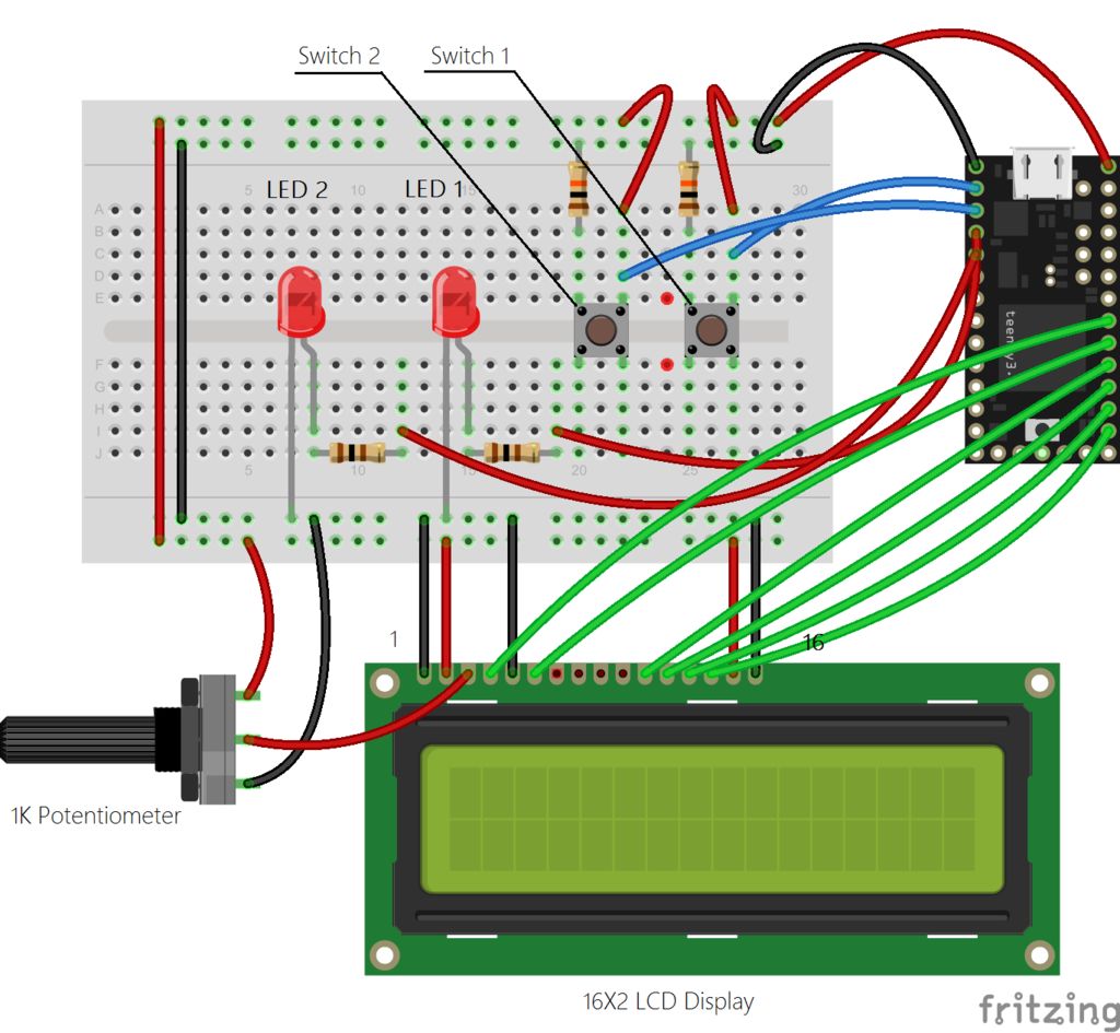
Before you start off with the main build, it’s much more convenient to test out the design and see if everything is working. So for this stage, we will set up 2 switches with the Arduino, on pins 0,1 as INPUT, and 2 corresponding LEDs for notification on pins 2,3 as OUTPUT. A 16X2 LCD Display can also be included in the circuit. Generally, an LCD display of this sort has 16 pins. Heed to the order of the pins, numbers 1 and 16 are usually printed as a guidance. The pinout for the LCD display as as follows:
- Ground
- Supply voltage for logic ( +5v supply )
- Operating voltage for LCD contrast ( middle pin of potentiometer )
- Instruction code ( pin 19 on teensy )
- Read/write signal ( not connected )
- Enable signal ( pin 18 on teensy )
- Data bus 7 ( not connected )
- DB 6 ( not connected )
- DB 5 ( not connected )
- DB 4 ( not connected )
- DB 3 ( pin 17 on teensy )
- DB 2 ( pin 16 on teensy )
- DB 1 ( pin 15 on teensy )
- DB 0 ( pin 14 on teensy )
- Ground
- Power supply for LCD ( +5V supply )
A Fritzing diagram is as shown.
– A 10k resistor is used with the switch as a Pull-down resistor. Meaning, whenever the switch is not toggled on, it is pulled to the ground, so that it is not affected by erroneous noise signal which may be present due to other active devices. Simply speaking, when the switch is off, the resistor ensures that it is off. Any value from 1k – 100k will do.
– Choosing the resistor value for your LED. The following tutorial explains how you can choose the resistor value for the LEDs you have.
There is another way to determine the required resistance. Use a 10k potentiometer, connect one wire from from the longer edge of the LED to the wiper, or middle pin of the pot. Connect a wire from either of the pins of the pot to one of the digital pins on the arduino. Now rotate the wiper till the LED glows sufficiently bright, then measure the resistance across the pins using a multimeter. This is a raw estimate of the required resistance.
Always use an LED with a resistor. An LED glows the brightest without one, but since there is nothing limiting the current from the arduino to the LED, the entire available current is transferred to the LED, which will ruin it in the long run.
Once the circuit is done, connect your arduino to your PC using a USB cable. Follow the instruction below, if you’ve never used an arduino before. This basically explains how to compile and upload an already existing code(or sketch, as they call it) onto your arduino.
Also, remember to set the device as a midi device.
Select “MIDI” from Tools -> USB type.
The code for this prototype is uploaded below. It is thoroughly commented and is self explanatory.
Now, we test if the circuit and code are functional.
Press both the buttons, do the corresponding LEDs light up ?
To test if the computer is actually receiving any MIDI signal from the button you just depressed, you need the software, MIDI OX, installed.
In MIDI OX, go to Options -> MIDI Device, and select your device. Mine shows us as Teensy MIDI.
Whenever, you press and release a button, an output similar to this should show up. Are you getting a similar output ?
If everything goes fine, we conclude that all the components and code are working fine, and we can move on to building an enclosure for the project.
 Prototype_code.ino