A good friend of mine who’s a teacher was doing quizzes in her class making students compete to answer questions… resulting in them complaining they raised their hands before the others.
I decided to give her this quiz show type buzzer for Christmas to solve her problems.
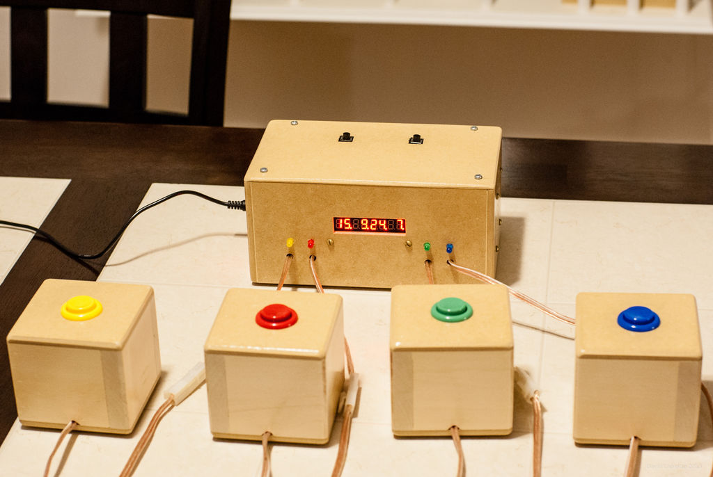
When one of the players press it’s button (the fastest player wins this), the led of the right colour lights up saying he’s in control… and no other buttons from the other players work, until the master of the game decides if the answer is good or not by pressing a little button on the main unit, giving a point or not to the player in control.
If you have any questions, comments, constructive criticism… don’t hesitate to write 🙂
If you like my build, please like the video on YouTube and subscribe, it would be nice 🙂
P.S. There is a little problem with the display that I couldn’t figure out how to solve. When playing a tune, the display doesn’t light up anymore, like if no current goes to it anymore… anybody has an idea what the problem could be or how to fix it in code ? See the video if you don’t understand what I mean.
Step 1: Components
- Rocker Switch
- ATmega328
- Ceramic Resonator 16MHZ
- 5V wall adapter power supply
- Barrel jack
- Hook-up wires (black, red, green, white, yellow)
- Heat shrink tubing
- Big buttons (green, blue, yellow, red)
- Some LEDs
- Serial 8 Characters x 7 Segment LED Display
- Prototyping board
- Tamiya connectors (male, female)
- Some resistors (1x100ohm (for the speaker), 5x150ohm (for the leds), 6x10KOhm (for the buttons))
- Push buttons (2)
- Speaker wire
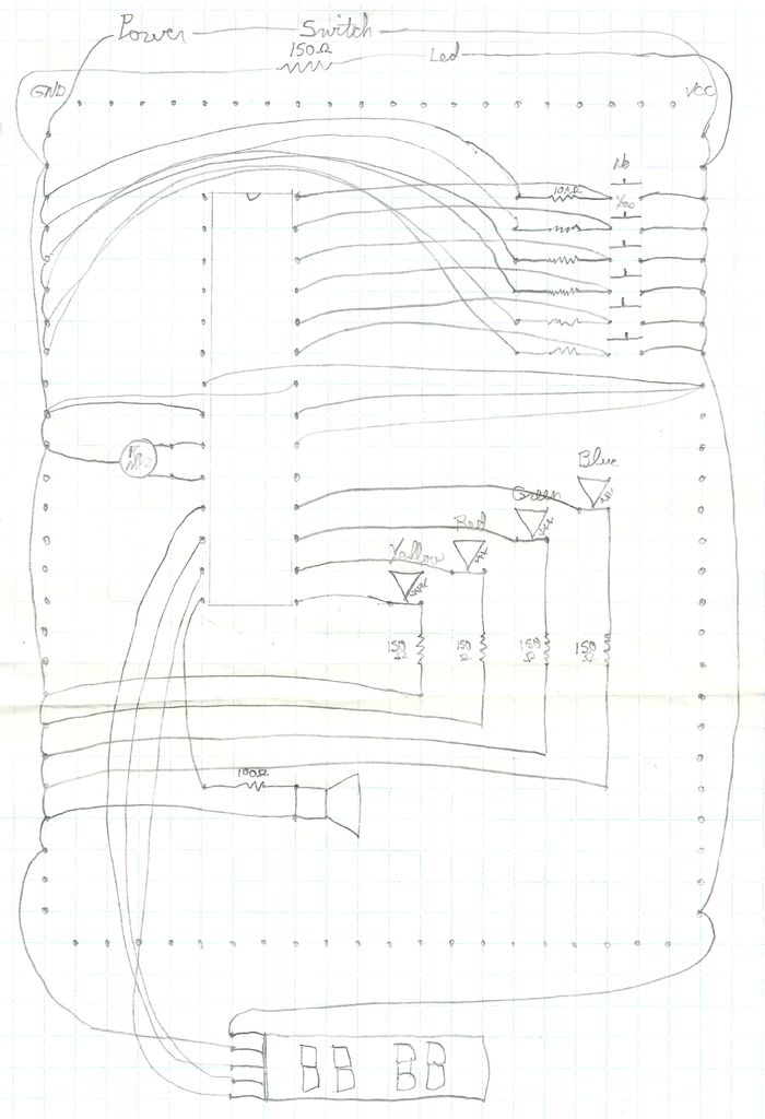
Step 2: The Plan
Sorry for my writing… I know it’s not a very professional plan, but if I have more time I will make a better one and replace it… feel free to ask me anything about it if it’s not clear 😉
Step 3: The Prototype
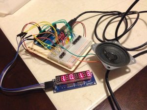
I’ve decided to try my idea with an Arduino prototype.
The different buttons are for each “team” and for the master of the game to accept or reject an answer, giving the point to the team answering the question or not.
The leds lit up to know which team can currently answer.
The speaker plays a little tune… but it’s not amplified, so it’s not very loud.
The display shows the current score for each teams.
Step 4: The Code
So… I’m including my code, but I’m not explaining it… and yes I know there is no comments… if you have questions, feel free to ask me, but I didn’t do this to make a programming tutorial.
First you need to include “pitches.h”… but to be able to include it, you need to get it from here… Arduino Tone Tutorial
#include “pitches.h”
Then let’s define some arrays to help ourselves for later when we need to use the 8 digits 7 segments display
// array to activate particular digit on the 8x7segment module<br>// it is the common anode of 7 segment
byte digit[8] = {
  0b10000000,  //digit 1 from right
  0b01000000,  //digit 2 from right
  0b00100000,  //digit 3 from right
  0b00010000,  //digit 4 from right
  0b00001000,  //digit 5 from right
  0b00000100,  //digit 6 from right
  0b00000010,  //digit 7 from right
  0b00000001   //digit 8 from right
};
<br><p>//array for decimal number, it is the cathode, please refer to the datasheet.
//therefore a logic low will activete the particular segment
//PGFEDCBA, segment on 7 segment, P is the dot
byte number[12] = {
  0b11000000,  // 0
  0b11111001,  // 1
  0b10100100,  // 2
  0b10110000,  // 3
  0b10011001,  // 4
  0b10010010,  // 5
  0b10000010,  // 6
  0b11111000,  // 7
  0b10000000,  // 8
  0b10010000,  // 9
  0b01111111,  //dot
  0b11111111   //blank
};</p>
We should also define some constants that will help us identify input and output pins later in the code
const int blueLEDPin = 12;
const int greenLEDPin = 11;
const int redLEDPin = 10;
const int yellowLEDPin = 9;

const int teamPinDiff = 5;  //to help with computations later<

const int blueButton = 17;
const int greenButton = 16;
const int redButton = 15;
const int yellowButton = 14;
const int acceptButton = 18;
const int refuseButton = 19;

const int speakerPin = 8;

const int latchPin = 7;  //connect to RCK of 8x7segment module
const int clockPin = 6;  //connect to SCK of 8x7segment module
const int dataPin = 5;  //connect to DIO of 8x7segment module

const int multiplexDelay = 1;

const int dotNumber = 10;
const int blankNumber = 11;
We also need to keep some variables to know what’s going on in the program
int currentTeam = 0;
int blueScore = 0;
int greenScore = 0;
int redScore = 0;
int yellowScore = 0;byte blueDigit1 = number[blankNumber];
byte blueDigit2 = number[0];
byte greenDigit1 = number[blankNumber];
byte greenDigit2 = number[0];
byte redDigit1 = number[blankNumber];
byte redDigit2 = number[0];
byte yellowDigit1 = number[blankNumber];
byte yellowDigit2 = number[0];
Then we setup the pin modes and the display
void setup()
{
  pinMode(blueLEDPin, OUTPUT);
  pinMode(greenLEDPin, OUTPUT);
  pinMode(redLEDPin, OUTPUT);
  pinMode(yellowLEDPin, OUTPUT);
  pinMode(blueButton, INPUT);
  pinMode(greenButton, INPUT);
  pinMode(redButton, INPUT);
  pinMode(yellowButton, INPUT);
  pinMode(acceptButton, INPUT);
  pinMode(refuseButton, INPUT);
  pinMode(speakerPin, OUTPUT);

  digitalWrite(blueLEDPin, LOW);
  digitalWrite(greenLEDPin, LOW);
  digitalWrite(redLEDPin, LOW);
  digitalWrite(yellowLEDPin, LOW);

  pinMode(latchPin, OUTPUT);
  pinMode(clockPin, OUTPUT);
  pinMode(dataPin, OUTPUT);
  digitalWrite(latchPin, HIGH);
}
And we create the loop function that will run after setup
void loop()
{
  ProgramLoop();
  WriteScore();
}
As you see, I’ve created functions to separate my code a bit better… so let’s create those functions
void ProgramLoop()
{
  if (currentTeam == 0) {
    if (digitalRead(blueButton) == HIGH) {
      currentTeam = blueLEDPin;
      PlayAnswerBlue();
    }
    else if (digitalRead(greenButton) == HIGH) {
      currentTeam = greenLEDPin;
      PlayAnswerGreen();
    }
    else if (digitalRead(redButton) == HIGH) {
      currentTeam = redLEDPin;
      PlayAnswerRed();
    }
    else if (digitalRead(yellowButton) == HIGH) {
      currentTeam = yellowLEDPin;
      PlayAnswerYellow();
    }
  }
  else
  {
    digitalWrite(currentTeam, HIGH);
    if (digitalRead(currentTeam + teamPinDiff) == LOW) {
      if (digitalRead(acceptButton) == HIGH) {
        PlayAccept();
        IncrementScore();
      }
      else if (digitalRead(refuseButton) == HIGH) {
        PlayDeny();
        ResetState();
      }
    }
  }
}
void ResetState()
{
  currentTeam = 0;
  digitalWrite(blueLEDPin, LOW);
  digitalWrite(greenLEDPin, LOW);
  digitalWrite(redLEDPin, LOW);
  digitalWrite(yellowLEDPin, LOW);
}
void IncrementScore()
{
  switch (currentTeam) {
  case blueLEDPin:
    blueScore++;
    if (blueScore > 9) {
      if (blueScore > 99) {
        blueScore = 0;
      }
      blueDigit1 = number[blueScore / 10];
    }
    blueDigit2 = number[blueScore % 10];
    break;
  case greenLEDPin:
    greenScore++;
    if (greenScore > 9) {
      if (greenScore > 99) {
        greenScore = 0;
      }
      greenDigit1 = number[greenScore / 10];
    }
    greenDigit2 = number[greenScore % 10];
    break;
  case redLEDPin:
    redScore++;
    if (redScore > 9) {
      if (redScore > 99) {
        redScore = 0;
      }
      redDigit1 = number[redScore / 10];
    }
    redDigit2 = number[redScore % 10];
    break;
  case yellowLEDPin:
    yellowScore++;
    if (yellowScore > 9) {
      if (yellowScore > 99) {
        yellowScore = 0;
      }
      yellowDigit1 = number[yellowScore / 10];
    }
    yellowDigit2 = number[yellowScore % 10];
    break;
  }
  ResetState();
}
void WriteScore()
{
  display8x7segment(digit[0], number[dotNumber]);
  display8x7segment(digit[0], blueDigit2);
  display8x7segment(digit[1], blueDigit1);
  display8x7segment(digit[2], number[dotNumber]);
  display8x7segment(digit[2], greenDigit2);
  display8x7segment(digit[3], greenDigit1);
  display8x7segment(digit[4], number[dotNumber]);
  display8x7segment(digit[4], redDigit2);
  display8x7segment(digit[5], redDigit1);
  display8x7segment(digit[6], number[dotNumber]);
  display8x7segment(digit[6], yellowDigit2);
  display8x7segment(digit[7], yellowDigit1);
}

void display8x7segment(byte digit, byte number)
{
  digitalWrite(latchPin, LOW);
  shiftOut(dataPin, clockPin, MSBFIRST, digit); // clears the right display
  shiftOut(dataPin, clockPin, MSBFIRST, number); // clears the left display
  digitalWrite(latchPin, HIGH);
  delay(1);
}
void PlayAnswerBlue()
{
  display8x7segment(digit[7], number[blankNumber]);
  beep(speakerPin, NOTE_C5, 100);
  delay(25);
  beep(speakerPin, NOTE_C5, 100);
  delay(25);
  beep(speakerPin, NOTE_C5, 100);
}

void PlayAnswerGreen() {
  display8x7segment(digit[7], number[blankNumber]);
  beep(speakerPin, NOTE_D5, 100);
  delay(25);
  beep(speakerPin, NOTE_D5, 100);
  delay(25);
  beep(speakerPin, NOTE_D5, 100);
}

void PlayAnswerRed() {
  display8x7segment(digit[7], number[blankNumber]);
  beep(speakerPin, NOTE_E5, 100);
  delay(25);
  beep(speakerPin, NOTE_E5, 100);
  delay(25);
  beep(speakerPin, NOTE_E5, 100);
}

void PlayAnswerYellow() {
  display8x7segment(digit[7], number[blankNumber]);
  beep(speakerPin, NOTE_F5, 100);
  delay(25);
  beep(speakerPin, NOTE_F5, 100);
  delay(25);
  beep(speakerPin, NOTE_F5, 100);
}

void PlayAccept() {
  display8x7segment(digit[7], number[blankNumber]);
  beep(speakerPin, NOTE_C5, 75);
  delay(10);
  beep(speakerPin, NOTE_D5, 75);
  delay(10);
  beep(speakerPin, NOTE_E5, 75);
  delay(10);
  beep(speakerPin, NOTE_G5, 75);
  delay(10);
  beep(speakerPin, NOTE_E5, 75);
  delay(10);
  beep(speakerPin, NOTE_G5, 75);
  delay(10);
  beep(speakerPin, NOTE_C6, 75);
}

void PlayDeny() {
  display8x7segment(digit[7], number[blankNumber]);
  beep(speakerPin, NOTE_A4, 1000);
}

void beep (unsigned char speakerPin, int frequencyInHertz, long timeInMilliseconds)
{
  int x;
  long delayAmount = (long)(1000000/frequencyInHertz);
  long loopTime = (long)((timeInMilliseconds*1000)/(delayAmount*2));
  for (x=0; x < loopTime; x++)
  {
    digitalWrite(speakerPin, HIGH);
    delayMicroseconds(delayAmount);
    digitalWrite(speakerPin, LOW);
    delayMicroseconds(delayAmount);
  }
}
Step 5: The Buttons
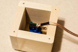
I made the buttons with some big coloured buttons and some speaker cables… you can use whatever kind of cables you want. I also added connectors to make it easier to transport by removing it from the main unit.
Step 6: The Main Unit
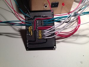
Here I’ve soldered everything together on the board and to all the components.
Then I’ve put everything in a wooden box that I built with the help of my dad, it’s custom made for this project and took a lot of time to built, but I’m really happy with the final product.
Oh and the Arduino has been replaced by an ATmega328 chip with a 16mhz ceramic resonator to save on cost and on space.
I’m also using a 5V power supply to power the whole thing… since the power should be more or less constant, I made the bet of not using a voltage regulator, but it would probably be safer to use one.
Step 7: The Finished Product
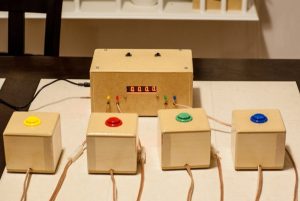
Here’s the Game Show Buzzer in action 🙂
See version 2… Now with Bluetooth here : https://www.instructables.com/id/Quiz-Game-Show-Buzzer-Bluetooth-Edition/
Step 8: Here’s How It Plays
If you like my build, please like the video on YouTube and subscribe, it would be nice 🙂