What it is…
- Type: Graphical (128×64) monochrome LCD with LED backlight
- Interface: Serial / SPI
- This is a good time to read the datasheet
- Available from: Adafruit, of course!
Introduction:
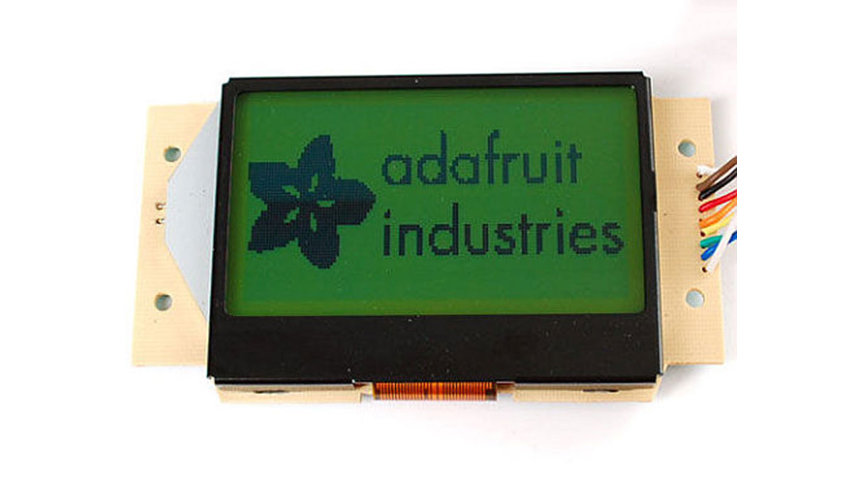
This mini-tutorial will go through the process of setting up a ST7565 LCD. These LCDs are graphical which means they can display pixels, not just text. This type of LCD in particular has 128×64 pixels, which appear dark gray on a green-blue background. They have a backlight but can also be used without the light on for daytime visibility.
 Another kind of LCD is the KS0108-type. These are not the same and are not compatible! Here are some comparisons
| KS0108 | ST7565 | |
|---|---|---|
| Voltage |
5V
|
3.3V
|
| Interface |
Parallel
|
Serial
|
| Data pins needed |
14
|
4 or 5
|
| Display size |
128×64
|
128×64
|
| Contrast adj. |
requires potentiometer
|
internal, no extras!
|
| Buffer needed? |
No
|
Yes |
As you can see there are a few differences.
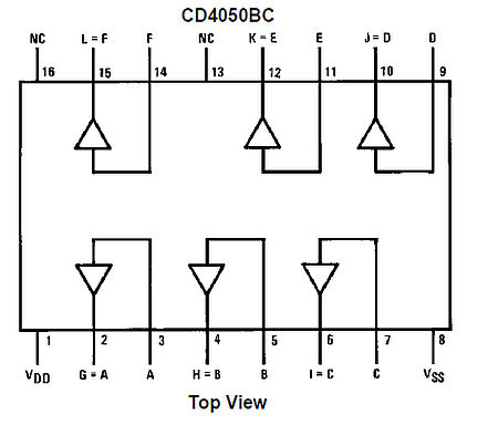
- For one the ST7565 runs at 3.3V not 5. This means a buffer chip or level shifting is necessary, you can use resistors or a chip like the 4050 (or equiv).
- Second, the interface is Serial (one bit at a time) instead of Parallel (8 bits at a time). This means it uses waaay fewer pins (yay!)
- The biggest downside is that you can’t read from the LCD in serial mode, only write. This means that the chip has to keep track of the display (the KS0108 lets you read or write). So whatever microcontroller you use will need to spend 1024 bytes (1Kb) of RAM on the display memory. For some chips this is a little and some its a lot – you will need to check the micro’s datasheet.
If you are using an ATmega168 or ATmega8 such as used in older Arduinos you must upgrade to a ‘328 to use this LCD. And if you’re using a ‘328 note that half the RAM is going to the display so you wont have a lot left over. This pretty much means you can’t use something with an SD card (like a Wave Shield or Data logger Shield at the same time you will straight-up run out of RAM and it will be weird so don’t bother).
Step 1: Get The Code & Wire It Up!
Get the code!
We’ve written a tidy library for both C and Arduinoese, if you aren’t using an AVR the C code is very portable and should take only a few minutes to turn into your favorite microcontroller.
Download it from github – click Download Source to grab it all. If you are using an Arduino, install the ST7565 folder which contains the library and an example sketch
Here are the wire colors and the pins they go to:
- /CS – Chip Select – White
- /RST – Reset – Blue
- A0 – sometiimes called RS – Green
- SCLK – Serial clock – Yellow
- SID – Serial Input Data – Orange
- VDD – 3.3V power – Red
- GND – ground – Black
- K – LED cathode – Brown
- A – LED anode – White
For more detail: ST7565 LCDs: Graphical LCDs