Ever wanted to have a Phone Book, controlled using a microcontroller, which is very easy to use, and you can use it while talking on phone, and is saving data on SD Card? then this instructable is for you. In this instructable you will learn how to make an arduino controlled Phone Book, and you can control it using only four buttons (Up, Down, Left, Edit), in this instructable you will also learn how to use LCD displays and how to store data on SD Cards.

Step 1: Parts
For this project you will need:
– Arduino UNO (Any ATmega based board will work, other boards will have different pins)
– SD Card (you can use any sd card but you must have SD Card adaptor)
– 8×2 LCD Display
– Breadboard
– Jumper wires
– Variable Resistor (to adjust contrast on LCD)
– 4x Pushbuttons
– 4x ~100nF capacitors
– 4x 1kOhm Resistors
– 3x 4.7kOhm resistors
– 3x 10kOhm resistors
– 1x 100Ohm resistor
– 1x power plug
– 1x diode (optional)
– 1x On/Off switch
– 1x Box
Step 2: Some info about Liquid Crystal Displays
Liquid Crystal Displays have many uses, they can be used in televisions, computers or other electric devices, they are also really easy to use. There are also many sizes of them, for example 20×2 (Note size AxB means A columns and B rows), 10×4 and so on, in this project I have used 8×2 LCD. So, Liquid Crystal Display Modules have 14 pins (but in this tutorial we need only 10, and only 6 pins go to arduino board), and 2 other pins (Anode +4.2V (you can connect it to +5V with 100 ohm resistor) and Cathode (Ground)) for LCD Backlight. So LCD pinout looks like this:
1 2 3 4 5 6 7 8 9 10 11 12 13 14
Gnd +5V V0 RS R/W E D0 D1 D2 D3 D4 D5 D6 D7
(In images look at LCD wiring schematic)
Pin 1: Ground Pin
Pin 2: +5V Pin.
Pin 3: contrast adjust pin, and it goes to potentiometer
Pin 4: is Register/Select Signal pin and it goes to arduino’s pin 7 (you can use any I/O pin)
Pin 5: is Read Write pin, in other words if it’s set to HIGH then it’s in Read mode but if it’s set to LOW it’s Write mode, because we only want to write on LCD we can just connect it to ground.
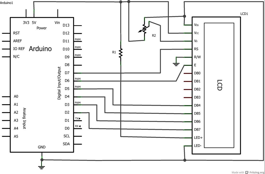
Pin 6: is Enable Signal Pin and it goes to arduino pin 6.
From Pin 7 to Pin 14: Data pins but we only need pins from 11 to 14.
So connect LCD Pins to Arduino Like that:
Pin 11: to Arduino pin 5
Pin 12: to Arduino Pin 4
Pin 13: to Arduino Pin 3
Pin 14: to Arduino Pin 2
Pin 15: Anode Pin, Connect to +5 V with 100 ohm resistor (Warning: Do not forget this resistor, otherwise you will damage your LCD)
Pin 16: Cathode Pin, Connect it to Ground
After Wiring is done you can connect your arduino to your computer and open new example sketch (File -> Examples -> LiquidCrystal -> Hello World), after opening sketch, before loop() you will notice this:
LiquidCrystal lcd(12, 11, 5, 4, 3, 2);
Change these numbers to this: (7, 6, 5, 4, 3, 2) (These numbers are I/O Pin numbers that are connected to LCD. Example: LiquidCrystal lcd(RS, E, D4, D5, D6, D7)) (NOTE: We are using this project also uses SD Card and SD Card only works at 13, 12, 11, 10 pins)
For more detail: Arduino Phone Book