In country like India most of the people are dependent on agriculture.For effective planning in agriculture weather forecast is of utmost importance.So farmers are always interested in the Weather Forecasts.As farmers stay in remote areas, they have to wait for the news updates in tv, radio or news papers.Unfortunately this weather information is not the accurate data of their local environment rather it gives data of nearest weather forecasting station.
Being a son of a farmer, I decided to monitor the local weather and inform to my father earlier.So that he can take early decision for his farm.
To make a weather station, I searched in Instructables and found a very nice project written by bram2202.
Thanks to bram2202 for this nice instructable.
You can see his project here
To make his project more powerful, I added some additional features.
My weather stations typically consist of two major parts:
1. The sensors that sit outside and measure temperature,humidity, rainfall, and barometric pressure.This data is send wirelessly through a RF transmitter module to the display unit.I named the entire module as Transmitter module.(Tx).
2. The display unit that lives inside in a convenient place so any one can read the external temperature,humidity etc. It equipped with a RF receiver to receive data from transmitter module.I named it as Receiver module (Rx).
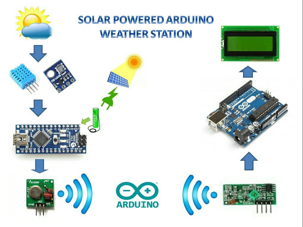
Both the module are run by the arduino micro controllers.
As the transmitter module is deployed in the field,we have to deal with the power management.It is impractical to run a long cable to provide power to the sensor’s location.This leaves relatively few practical options.
1. Connecting directly an Arduino board to a battery. Though it sounds good and obviously it would work, but your battery would be depleted in a matter of days because some components like voltage regulators,power led and USB interfacing chip in the arduino board are always drawing power.
But now a days high capacity battery packs are readily available in the market.Solar panels are getting more efficient and cheaper. Adding a boost converter in the circuits extract every last drops of juice out of battery.
2. Putting the arduino to “sleep mode” to consume even less power.
You can see it in the step-11 and 12.
In this guide I will teach a new skills on how you can make a solar powered battery pack for your arduino and how arduino power consumption can be optimize by putting it in to sleep mode.
By using the above technique you can run your sensor related or any other stand alone arduino project for a long time.
Step 1: PARTS AND TOOLS REQUIRED :
PARTS :
1.Arduino Uno (eBay)
2.Arduino Nano (eBay)
3. DHT11 (eBay)
4.RF transmitter-Receiver pair (eBay)
5.20×4 LCD display (eBay)
6.LCD I2C module (eBay)
7. 3.7 V Li Ion Battery /2 AA Ni Mh rechargable Battery (eBay)
8.Boost Converter (eBay)
9.Li Ion Battery charging board (eBay)
10. Battery Holder (eBay)
11.Solar Panel (eBay)
12.Resistor (10K)
13.Diode (IN4007)
14.Jumper wires/Wires
15.Bread Board
16.22 AWG solid core wire ( for making antenna)
17.Scotch mounting pad and tap
TOOLS :
1.Soldering Iron and solder
2.Glue gun
3.Hobby Knife
4.Drill
5.Wire cutter/Stripper
Step 2: SOLAR POWER
Why Solar Power ?
The main draw back of battery operated device is that it will depleted after a certain time.This draw back can be eliminated by using a natural resources like solar,wind or hydro energy.The most obvious free source of energy to recharge the battery is solar energy. It is a relatively simple, cheap and requires very less skill .
Among the rechargeable battery nickle metal hydride (NiMH) and Li Ion battery are widely used for battery operated device.
Facts on Battery Charging :
The thumb rule for charging Ni Mh batteries is 1/10th (commonly known as C/10). To charge the battery pack at 1/10th its rated current requires 16 hours of charge time( You can see the picture).The solar panel receives optimal sunlight for only four hours per day, from 10 a.m. to 2 p.m. Thus, a totally ideal system would require four days to fully charge the battery pack.
What is C/10 ?
For example we have a 2xAA–sized 1300mAh battery pack that is rated at 1.2 volts per cell. With cells in series, our pack outputs 2.4 volts and 1300mAh.
Here capacity C =1300mAh
C/10 means 1300/10 =130mAh
So to charge the above battery pack we need a higher voltage ( 2.4 to 3 V) with a maximum current of 130mAh.
As per C/10 rule it requires 16 hours to fully charge the battery pack.
You must be ask,what will happen if we increase the current (>130mAh) ?No doubt your battery will charge faster.But the life of the battery will be reduce.So my advice is to keep the current bellow the C/10 value.
Step 3: How to Choose the right solar panel
The main source for powering the sensor module is solar panel.So it must be able to provide current for powering the arduino as well as current to charge the battery pack during the day.As per my experience it is the most challenging part for a novice user.
Don’t worry these are the following tricks which can help you to buy a right solar panel.
1. Voltage : Choose 1.5 times the battery pack voltage
2.Current : Current taken by the Arduino + current for charging (should be
Example :
A battery pack is made of 2 AA Ni Mh battery.
Battery voltage = 1.2 x 2= 2.4V
So required voltage for solar panel =2.4 x 1.5 = 3.6V
By taking some margin we can choose a 4V solar panel for it.
The sensor module along with arduino taking 100mAh current.
Battery capacity is 1300mAh
C/10 = 130mAh
Solar panel have to provide current 100mAh for arduino along with a current not more than 130mAh.
Lets take 100 mAh for charging the battery
Total current required = 100+100=200mAh
From the above calculation it is clear that we need a solar panel of 4V and 200mAh.
The following table shows the solar system configuration relationship between storage batteries and mini solar panels.
Battery —-> Solar Panel
1.2V ——> 2V ~ 2.5V
2.4V ——> 3.5V ~ 4V
3.6V ——> 5V ~ 6V
6V ——> 7.5V ~ 9V
12V ——>15V ~ 18V
Note : It is not the strict rule for choosing the exact rating solar panel,rather it is approximate rating .I write as per my experience.
Step 4: Ni Mh Battery Charger :
To power a arduino we need 5v.There are two options
1. Use a 4 AA battery pack :
Total voltage =1.2V x4=4.8V (nominal ) but when it is fully charge,voltage is more than 5V.
This is not efficient.
2.Use 2 AA battery pack :
Total voltage =1.2Vx2 =2.4 V
In this case we have to raise the voltage level to 5V by using a voltage booster circuit.
I recommend to use this pack.It is reliable and efficient.
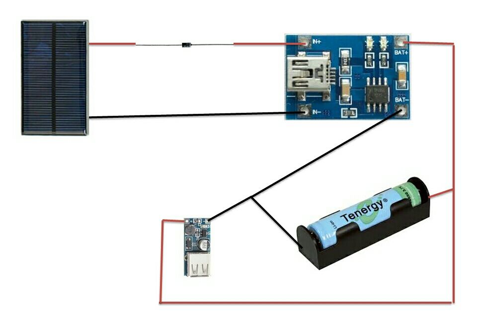
Charging Circuit :
Standard sized nickle metal hydride (NiMH) cells need simple charge circuit.
You only need a solar panel, diode, the batteries, and a battery case and wires.
4 AA battery pack
Solder the positive terminal of the solar panel to the positive terminal of diode.
Solder the negative terminal of diode to the positive terminal of battery pack.
solder the negative terminal of the solar panel to the negative terminal of the battery pack.
See the above picture for soldering.
2 AA battery pack
As the battery pack voltage is not sufficient in this case, we have to use a booster circuit to make 5V for arduino.
For more detail: SOLAR POWERED ARDUINO WEATHER STATION