History and Story
In the 1950s, 1960s, 1970s, 1980s and even up into the 1990s phone phreaking was an amazingly cool way to explore an unknown world of phone switching networks. To “phreak” a telephone switch, can be done by using frequencies, or tones to manipulate the switching hardware. In doing so, taking control of the hardware was simple and gave the “phone phreak” the power of an inward-operator.
Blue Box
“The blue box is an electronic device that simulates a telephone operator’s dialing console. It functions by replicating the tones used to switch long-distance calls and using them to route the user’s own call, bypassing the normal switching mechanism. The most typical use of a blue box was to place free telephone calls. The blue box no longer works in most western nations, as modern switching systems are now digital and no longer use the in-band signaling which the blue box emulates. Instead, signaling occurs on an out-of-band channel which cannot be accessed from the line the caller is using (called Common Channel Interoffice Signaling (CCIS)). The blue box got its name because the first such device confiscated in 1961 by Bell System security was in a blue chassis.” – ProjectMF.org
Around the mid 1950s, Bell decided to publish an article on In-Band Signal Frequency Signalling (I swear they knew the whole time what would happen!) which “leaked” these frequency specifications. This led to hardware hacking enthusiasts and hobbyists, just like you and me, into creating their own multi-frequency tone synthesis devices called blue boxes. The frequencies are played at the same volume and for specific durations. For example, to dial a “1” as an inward operator, we would use 900Hz + 700Hz sine waves played for 66ms. If we stored digits we would play them for 66ms with 66ms pauses in between. The * and # keys are referred to as “KP” and “ST” respectively. And the only single frequency tone used is for seizing the trunk which is 2600Hz (this is what the original hacker quarterly “2600” magazine is actually named after). This is often referred to as “supervisory signalling,” or “seizing the trunk.”
As time went on, the older switching technologies started to fade out and the new packet-switched networks of today became more prevalent. This led to the decline (sometimes people say “death“) of phone phreaking. In-band signalling (sending signals through the mouth piece of the phone handset) was good for gone. That is, until a brilliant phone phreak and hacker named PhiberOptik (Mark Abene) had the great idea of emulating the phone switches of old by hacking the open source Linux Asterisk PBX. In doing so, he made the Zaptel mechanism (used in older versions) recognize single and multiple frequency tones. He gave the presentation at H.O.P.E. (Hackers on Planet Earth) in 2006 and the Asterisks patches were then released on his website Project.MF.org Since then, there has also been a resurgence of antique telephone hardware into what is known as the Collector’s Network. These invaluable resources empower anyone who ever wanted to phone phreak, explore, and control phone switching equipment but never got the chance to, the opportunity.
Let’s Get Started!
I have come to you Instructables.com for the chance of spreading the word that phone phreaking is, in fact, alive and well! So, with this history and brief introduction in our belts, we can now move on to making our own blue box to phreak with.
Step 1: Arduino IDE and Library Setup
The advent of the Arduino put power into the hands of the same type of folks who originally designed the first blue boxes. We can write our own micro-controller code, use easily obtainable Radio Shack parts to design unique hardware and much, much more. There are many ways we can design our blue boxes and this article will only cover a simple few of them.
Tone Library
First is the Tone library – square wave – synthesis device. This device can be made using the Arduino Micro ATMega32u4 based chip with the Arduino (external) Tone library. The library needs to be modified to work with the ATMega32u4 chip and a modified version can be downloaded on my website here. This library and chip have only been tested with the Arduino IDE version 1.0.5 Now that we have the library and chip, we now need a simple schematic that we can use with a keypad.
Keypad Library
The Arduino Keypad library can be found here. All libraries need to be in the Arduino “libraries” directory located in the base of your IDE installation. e.g. C:\Users\trevelyn412\Documents\Arduino\libraries Most of the time this is as simple as extracting the library from a zip file, but check your library’s documentation if advanced instructions for installation are required.
TMRpcm Library
Finally, the TMRpcm library is used by schematic 2 for playing WAV files from our second blue box. The author of this library was kind enough to help me via email as I was having difficulty with the non-existent SeeedStudio v3 SD card Shield documentation. It plays mono files at 32khz and below (I use 22khz) at 8 bit. There are however a lot of advanced functions and code optimizations that we can do by editing the pcmConfig.h header file, such as allowing a larger buffer space as we uncomment and change the line,
#define buffSize 128 //must be an even number
Also, by storing a single frequency WAV file onto the SD card, we need to lower it’s actual cycles by 25. This means in Audacity, generate a tone for 2575hz rather than 2600 for supervisory signalling.
The sounds I have created are all in the directory “sounds” located at the root of the micro SD card. There are several notes by the Arduino community for storing files and accessing them via Arduino libraries located here. These are very important to follow by.
Hardware Required
In these tutorials I use the following parts,
- Simple 10k Ohm resistors
- Momentary push-buttons
- LED lit toggle power switches
- Arduino UNO && Arduino Micro
- SeeedStudio v3 SD Card Shield
- BLUE Advantus Super Stacker Crayon Boxes
- Blue LEDs
- 100k Potentiometers for volume
- 2.2uF non-polarized capacitor (optional)
- 9V batteries (one schematic uses 2 in parallel
- Rotary dial mechanism from old phone
- Velleman 4×4 keypad
- 150 Ohm telephone receiver speaker part #SD150(ph) (for optimal output)
And anything else is optional. The LEDs are optional and hardware with LEDs like the power switches are also optional. Changing the schematic for accommodate for these should be very easy.
Arduino Experience
This tutorial assumes very basic knowledge of the code used by the Arduino and how to set up a basic project using a bread board. I do, however go into instructions on how to manage these projects into boxes of their own, but that requires soldering and solder experience, in most cases.
Step 2: 1st Schematic
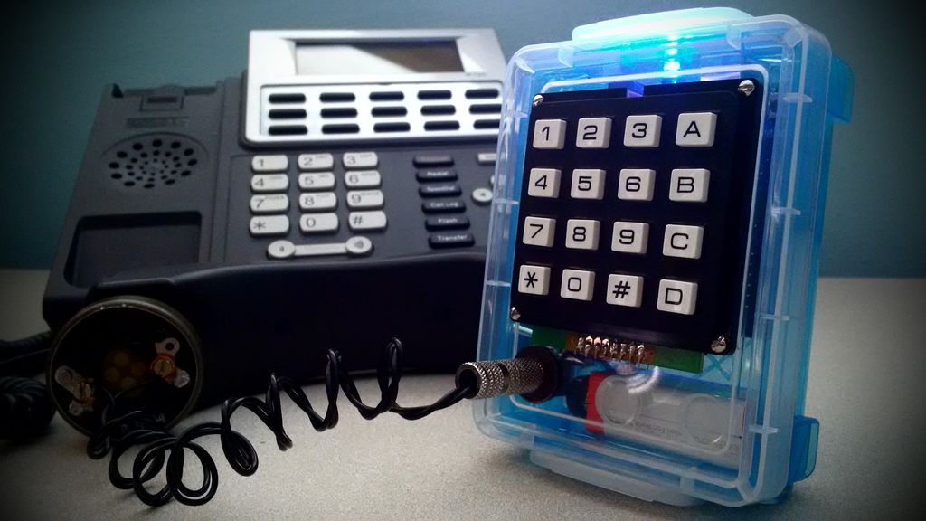
I will be showing you how to construct the two boxes that I have personally made using the Tone synthesis library and the Arduino UNO / SeeedStudio SD Shield – TMRpcm WAV file player versions. For two of these tutorials I will be using the Velleman 4×4 keypad. This is a very study keypad which comes with a pin-out diagram on the back of the package for easily hooking it up to the Ardiuno.
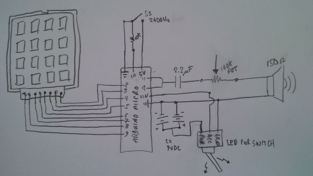
In the image above is the simplest schematic in this series. It uses only a 4×4 keypad, a single supervisory signalling button, a volume knob (potentiometer), and a stylish LED-lit power button. The momentary pushbutton requires the pin 10 also have a 10k Ohm resistance to ground. The other side of the switch goes directly to the 5V pin as we can see form the simple schematic. Developing this hardware layout is simple, but debugging can take hours. It’s best to use a simple bread-board for those unfamiliar with schematic diagrams or electronics.
For more detail: Arduino-Based Blue Box (Phone Phreaking)