One quick fore note: this is my first Instructable and my first large Arduino project, so if you see any stupid errors or have an idea of how things could be done better, then please let me know.
Now that that’s out of the way I’ll begin, I started designing this around September last year as my A2 Product Design project and thought that it might make a good Instructable once it was finished.
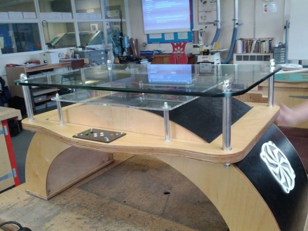
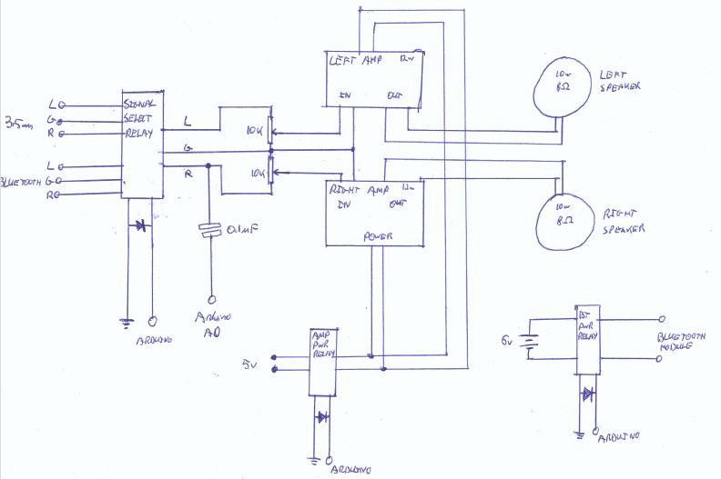
The design of the table aspect was inspired mainly from another table I had seen with a similar arched shape but with a flat top, and the electronics were mainly inspire from this coffee table, although I wanted something easier so I used a 16×16 single colour matrix and two LCD displays on my table, there is also an audio amplifier and Bluetooth receiver for playing music through the table.
So that’s all there really is to say, most of the things that are part of the finished product were thought up along the way, but here are some of my original designs anyway.
Step 1: Main Arch Assembly – Part 1
However there is no reason this couldn’t be done using a hand router, so I’ll include some imaged of all the parts and their sizes as well.
The first set of parts was the MDF panels to make up the main arch for the table, this was two arched panels with slots routed into them and smaller panels that fir into the slots between the two panels.
After the parts had finished being machined, they require a quick sand down to remove any loose MDF fibre then they are ready to be assembled and glued, I used standard PVA adhesive and clamped the two arched panels around the smaller panels while the glue set, but you could get similar results by using some wood screws in the joints to keep them secure while the glue sets.
If you do want to adapt the design of the table, the main thing to keep in mind is the space required for all of the electronics and how they will be mounted internally, always be sure to leave more space than what you think you will need.
The design I had chosen contained 5 internal sections, of which 4 of them would hold MDF panels, each of which held some of the electronics (I’ll call these “blades” because it sounds cool).
Also I have included a ZIP archive of all the drawings I used with CNC machines in making the table on this step.
Step 2: Electronics – Part 1
The electronics is separated into four main sections: the main micro-controller, the audio part, the LED matrix driver and the two LCD’s. I’ll cover the micro-controller first as it seems the logical place to start.
I used a clone Arduino Mega board in the table mainly because of the number of pins needed for all of the other electronics, for making connections between the Arduino and other parts of the table I used 10 pin ribbon cable for which I made breakout boards for both of the endpoints, looking back it would have been neater to combine each of the breakout boards at the Arduino end into one shield, but time was running out to get the electronics done so this never happened.
I’ll cover the more complex electronics in further steps, but it’s worth mentioning the more simple parts here, firstly, depending on what type of power supply you intend to use you may need to include a power regulator and/or filter circuit after the main power input, since I was using a regulated power supply that output the correct voltage for the Arduino, etc. I did not have to worry about this.
The only other part that is worth mentioning is power distribution inside the table, I did this simply with a row of terminal blocks screwed to the inside of the table, the connections were make using the push in style connections (not sure what the correct name for those are), I also had two capacitors (rated at around 1000 micro Farads at 35 V each) connected to one of the outputs of this in order to stabilise the power supply, as in early testing I had problems with the Arduino reseting when the relays drew too much inrush current as they switched on.
Attached on this step are all of the PCB designs I used in making the electronics for the table, feel free to use them, although they could be combined into a single shield to make your life easer, looking back, I really wish I had done this.
Also I have realised that on the block diagram I did not include the button panel, sorry about that.
 CoffeeTablePCB.zip20 KB
Step 3: LED Matrix
The LED matrix was most defiantly the most complex part of the electronics (although that does not mean it was difficult to get working, in fact this is the only part that worked perfectly first time), this compromised of 256 individual white LEDs arranged in four 8×8 matrices each controlled by a MAX7219 (however it is worth noting that the MAX7221 would be a better option for this project as the MAX7219 is prone to interference from the audio system via the ground line, they are both pin by pin compatible so there should not be any modifications required to make this change).
The matrix is held in position by an Acrylic laser cut mount, this was also used to hold the LEDs in place whilst they were being soldered, it is hard to explain how an LED matrix is constructed through text only and I don’t have any photos from when I make the matrix, but there is a pretty good explanation of how to construct one on the Arduino Playground (which is where I refered to when building mine), basically as long as all the anodes are all in the same row and the cathodes are all in the same column, and there are no shorts between them you shouldn’t have any problems.
The matrix driver PCB compromised of the four MAX7219s, two filter capacitors per 7219 and a current limiting resistor per 7219, there are also a lot of wire bridges on this PCB as it was supposed to be just a prototype, but I ran out of time and patience to try to design the PCB layout more efficiently, I used this guide on the Arduino playground to construct and wire up the LED matrices to the driver ICs, it also details how the value of Iset (the current limiting resistor) should be chosen.
The driver PCB is connected to the Arduino via a 3 wire SPI interface and controlled using the LedControl library on the Arduino, the matrix is quite quick to respond considering there are four cascaded devices and I was pretty pleased with the results I got from my matrix, even though there were 4 LEDs that were faulty.
[box color=”#985D00″ bg=”#FFF8CB” font=”verdana” fontsize=”14 ” radius=”20 ” border=”#985D12″ float=”right” head=”Major Components in Project” headbg=”#FFEB70″ headcolor=”#985D00″]Arduino
LED Metrix
Audio system
Liquid Crystal Display
Web Service[/box]
For more detail: Interactive Arduino Powered Coffee Table