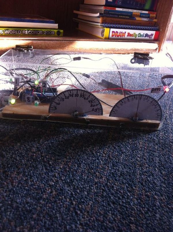
I was inspired by the digital/ analog clock to make my own special clock as my second instructable. I browsed the internet and found that servo clocks are rare and binary are common. So i decided to combine the two and this is what I made. I know it looks crappy but I’m an amateur and its decently accurate the worst I’ve seen it is a minute forward or behind. It even tells if its am or pm. I hope you all enjoy this. If you have any question please feel free to comment. I’m on instructables daily.
Step 1: Supplies
28cmx11.5cmx1cm piece of of wood. 28cmx9cm(2),11.5cmx9cm(2), and 28cmx11.5cm(1) Plexiglas. two small hinge pairs. Screws. Ruler with metric units. Sharpie. Two sewing needles 1.75 in long. Thin copper wire. Arduino(preferably mini or nano, doesn’t really matter). Insolated wire. Scissors. Card stock paper. Protractor image file(included). 5 100 ohm resistors. 4 same color and 1 different color LEDs. 2 small servo motors http://www.jameco.com/webapp/wcs/stores/servlet/Product_10001_10001_2150416_-1. glue gun. Clippers.
Step 2: The Body
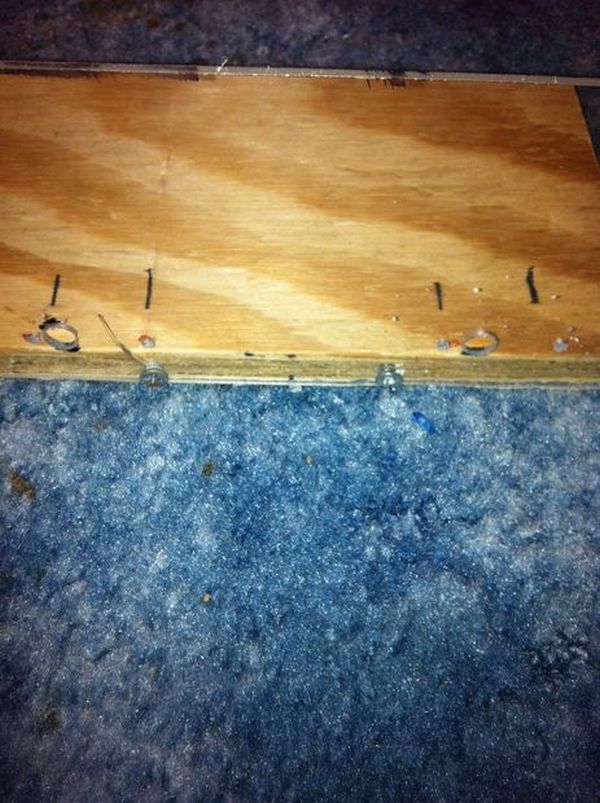
Cut out a piece of wood and 5 Plexiglas pieces that fit the dimensions from the supplies list. On the long sided Plexiglas panels drill 3 holes across the bottom. On one of those two panes make two pairs of holes to fit the hinges. On the other drill holes as shown in the photo. On the short sided Plexiglas panels drill two holes at the bottom. On the top piece Plexiglas panel drill two pairs of holes to fit the hinges. The holes on the bottom of the side panels will screw to the wooden base. Pre drill where the holes will so that its easier to screw in the screws. Use sharpie to mark where holes will be.
Step 3: Servo Holes And Protractor Displays
Screw in the front panel and starting from the right end line up a protractor cut out. Mark where it ends measure another 1cm and line up the other and mark where it ends. With the two protractors lined up take the servos and line up the attachment wheel with the cut out semicircle on each protractor. Mark on the glass where that is. From where you marked keep the servos in place and trace the key hole shape of each servo on the the other side of the plexiglas. On a table take the protractors and line up the semicircle with the attachment wheel and trace half of the key hole on the protractor and cut it out. Might want to look at photo for reference. Glue servos in place with wire connecting facing left. Use sharpie to make second marks every 3 degrees as shown. Attach protractors with tape.
Step 4: Clock Hands
Take 4 in of copper wire and thread them as shown.
Step 5: LEDS
Put the different colored led in the the corner hole. Put the other 4 same color led into the holes to the right of the protractors. Attach a resistor to each cathode by solder or twisting and glue them in place
For more detail: Binary/ Analog Clock