This is a tutorial for using the 7-Key Slider/Wheel Breakout from Rachel’s Electronics.
I’ll show you how to solder up the header pins for maximum usability. Rachel’s has the QT1106 datasheet on their site, and a great arduino library for this breakout.
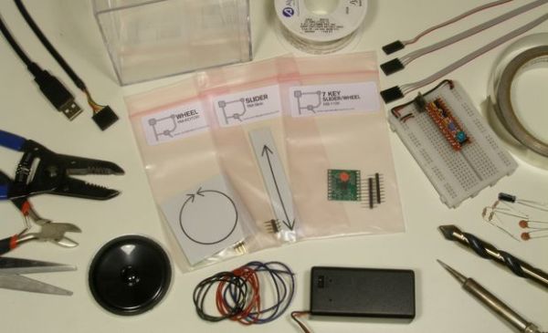
The kit from Rachel’s Electronics comes packed with cool stuff:
QT1106 breakout with header pins
Slider Module with header pins
Wheel Module with header pins
1 3-position 12″ jumper cable
2 4-position 12″ jumper cables
10″ of pre-tinned conductive tape
Our project will build a 7 touch key synthesizer and the slider will select different musical keys to play in. Links to libraries are included, and working code examples for testing your work and the final synth player as well. Let’s get started!
Step 1: Soldering The Top Header Pins
Check the orange dot on the breakout board to orient yourself.
We will be soldering the header pins in two steps:
- First, the pins on the top side that connect to the jumper cables.
- Then the pins on the bottom side that go into your breadboard.
Here we go.
Cut the header pins into sections. I find that using a wire snip is the best method.
The two header rows that come in the kit have 9 pins. Break one into two sections: 2-pins and 7-pins. These will go on the left side of the board. Now break the other row into 3 sections one 5-pin, one 3-pin, and one lonely single pin.
Now we’re ready to setup and solder the headers onto the breakout. We will do this in two stages, The first stage will flip the board upside down and solder the top pins in place. The 7-pin row goes into the holes labeled KEY1,KEY2, KEY3, KEY4, KEY5, KEY6, KEY7, and the 3-pin row into the holes labeled SNSA1,SNSA2,SNSA3.
The best way to solder in header pins is to put the pins into a breadboard first, then you can drop the board on and you’ll know the parts are all lined up nicely. Check the pictures below to see how the pins get laid out for this first step. Then place the breakout upside-down onto the pins as shown.
- Make sure to examine the pictures closely so you get it right!
But that’s not all. The GND pin needs to be accessible from both sides of the board. So strip and cut a piece of wire long enough to extend on both sides of the breakout
.
Remember that the breakout gets placed upside-down in this step. Warm up your iron and solder those headers! I have pics below of the finished solder points for you to follow.
Pull the breakout out of your breadboard very carefully. Rocking it back and forth slightly can help ease it off. Now take that length of insulation that you stripped off to make the GND pin and cut two tiny pieces that will serve to insulate either side of our GND pin.
Great! on to the next step.
Step 2: Soldering the Bottom Header Pins

Soldering the bottom pins next.
Again, it is easiest to place the header pins into your breadboard first. And because this is the last soldering step on the breakout, I’m putting the pins right where I want my breakout to be in the final circuit. Note in the pictures how I’m arranging my headers. I have two images that show the finished breakout from each side, so you can see how they are all arranged.
Maybe there is something cool that can be done with the lonely header pin that is left???
Step 3: Lashing the Breakout to the Arduino
The QT1106 IC uses Serial Peripheral Interface (SPI) protocol for communicating pin states, slider position, and user programming. I’m using the Ardweeny from Solarbotics for this instructable, but it will work with any Arduino platform.
These are the pin connections that we need to make for SPI:
- Pin Name Breakout Arduino
- SCLK 11 Digital 13
- SS 12 Digital 10
- MOSI 13 Digital 11
- MISO 14 Digital 12
There are also two pins used for something called ‘Handshaking’ where each device confirms that they are ready to communicate. The pin connections are:
- Pin Name Breakout Arduino
- DRDY 10 Digital 9
- CHNG 2 Digital 8
When the QT1106 decides that a sense event has occurred (touch, release, or slider movement), it sets the CHNG pin HIGH. This signals the Arduino that it should ask for new key and slider data via the SPI interface. When the Arduino starts the SPI, it first has to wait for the DRDY pin to go HIGH, otherwise, the QT1106 will miss all or a part of the communication. ALL OF THIS IS TAKEN CARE OF IN THE LIBRARY! THE LIBRARY WORKS HARD… SO YOU DON’T HAVE TO!
The last thing that you need to do is drop a couple of caps across the rails. These are Power supply conditioning capacitors, and they should be placed right next to the breakout +V and GND pins. I’m using 1uF, but 2.2uF will work just as well. If you don’t have these in place, your sensor will go a little crazy and spit out a lot of noise and spurious touch signals!
Step 4: Setting Up the Speaker
Speakers rarely come out of the box with wires attached. Unless you’re taking them out of a boom box ;D Here’s a quick run through wiring up a speaker for use in a breadboard.
- Use stranded wire. Please. Nothing is as sad as a finished project that quits working because one wire broke. Electronics connections that are expected to move around are made with stranded wire because it has a much longer bend life that solid wire.
Once you get your wire stripped and twisted up, an easy way to make this connection is to pre-tin the wire and the solder tabs on the speaker. You will have to tin the wire in order to get it into the holes in your breadboard, so you might as well tin everything, and then quickly make the connections here’s how:
- Pre-tinning is simply the process of applying some solder to a part or lead or bit of wire prior to making a connection. Hold the tip of your iron on the stranded wire end, and as it comes to temperature, put some solder there. Not too much!
- Once you have the pads on your speaker connections and the ends of your stranded wire tinned, it’s time to make the connection. Hold the wire up to the speaker connection and cut off any excess wire. You don’t want to accidentally short your signal against the body of the speaker. If your cut removes your pre-tinning, you didn’t tin enough. Do it again.
- Now you can hold the wire in one hand, and press the two pre-tinned parts together with your soldering iron. Once the parts melt together, remove the iron, and hold the wire still until everything solidifies.
Step 5: Lashing the Speaker to the Arduino
I am using the Tone library located here. Yes, I know there is a tone() command native to the arduino language since version 0018, but that one only allows you to output one tone at a time. This library will allow up to three tones at a time on the ATmega328, and I want to be able to make simple chords on my synthesizer. Instructions for installing the library in a further step.
- It turns out that you can indeed output up to 3 separate tones on an Arduino with this library. However, the 3rd tone instance is driven by Timer0, a hardware timer, that is used by Arduino to make millis() happen. Timer0 also makes delay() possible, and so when you incorporate the 3rd tone, you get hung up when you try to delay(). I like to delay() and I know you do too. So, this synth will let you play 2 note chords, and still let you delay() Yipee!
The Tone library lets you out put audio frequency on any digital pin. I’m using digitalPin 2 and digitalPin 3 for my audio output. Many tutorials will tell you to put a resistor between the digitalPin and one wire of the speaker. This works well to control the volume level. I’m using 1K resistors here. If you use 100ohm resistors, it will be very loud indeed!
The other wire is often connected directly to GND. I don’t want you to do that any more. I want you to put an electrolytic capacitor between the speaker and GND. The value of your capacitor should be 4.7uF or 10uF. Your choice. This is called an AC coupling capacitor. It will protect your speaker from DC current that could damage it, and allows the AC audio signal to get through. Trust me, it’s better.
For more detail: 7-Key Slider/Wheel Tutorial with Synthesizer