These are step by step instructions for assembling the 8×8 LED Board kit from moderndevice.com.
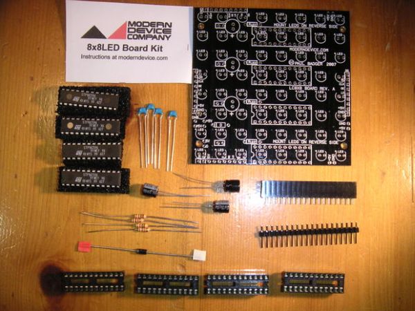
I had never played with LED displays before using this kit. I suggest reading through all the assembly steps BEFORE starting to solder because assembly order DOES matter with this kit.
Overall, this is a very simple assembly. It does have a few points which require special attention.
Step 1: Solder the LEDs
This is, by far, the most time consuming part of assembly.
Pay special attention to the polarity of each LED and make certain you have no cold solder joints.
You will be placing IC sockets over several of the solder joints and, if you get something wrong, it will make repair very difficult.
I chose green LEDs as they were the cheapest I could find. You may use other colors, but be aware of current requirements both in resistor choices and power supply.
The LEDs are placed on the NON-printed side of the board. I got ahead of myself when I first started and put a couple of rows on the wrong side of the board. De-soldering is NOT fun!
Moderndevice.com describes the following testing procedure for the LEDs. Truth be know, I just went through and closely examined the solder joints and orientation of each LED before the next step. If you skip testing, be aware you may find yourself with a complicated de-soldering project if something goes wrong.
Testing:
Clip a 470 – 1000 ohm resistor into a black alligator-clip test lead. Connect the other end of this test lead to the ground side of a 5-6V power supply. Next connect one end of a red colored alligator clip test lead to the positive, +5V side of your power supply. Clip the other end of this red, positive lead to one of the “+5V” labeled holes on the side of the 8x8LED board. Looping a piece of wire through the hole and twist it back on itself, will make a convenient terminal to which to clip the positive test lead.
Using the far end of the ground-lead resistor as a probe, carefully light up each LED in order. This can be done conveniently from the pads on which the driver chips will eventually mount.
Step 2: The capacitors
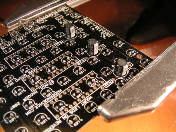
Observing correct orientation, solder in the three 47 ufd, 25 volt electrolytic capacitors.
Step 3: The IC sockets
Place the IC sockets on the board and solder just two leads. Check the positioning of the sockets. The notches on the sockets should face the capacitors.
When you are happy with the placement of the sockets, finish soldering the leads.
Step 4: The resistors
Solder in the four 1k ohm resistors. Orientation does not matter.
1k resistors are provided with the kit and used for 20mA LEDs. If you use LEDs with a different current draw, different resistors will be needed.
Step 5: More capacitors
Solder in the four .1 ufd (104) monolithic capacitors. Orientation does not matter.
Step 6: The ICs
Insert the ICs in the sockets paying close attention to correct orientation. The notch in each chip should face the capacitors. You will likely need to bend the leads a bit to get them to fit in the sockets.
For more detail: Assembling the 8×8 LED Board Kit