In this instructable, I will show you how to make a simple Simon Says Game using an Arduino. it’s not just simple but we can get a psychological benefit. I have a bad memory to remember something fast or a new things. So this project really suitable for someone like me. hahaha
 We’re gonna using some basic electronics built on top of an Arduino. When the project is finished you will have a working simple circuit that fun to play.
This is the video of my Arduino – Simple Simon Says Game
(change the quality for a better view)
Step 1: Parts and Tools
[box color=”#985D00″ bg=”#FFF8CB” font=”verdana” fontsize=”14 ” radius=”20 ” border=”#985D12″ float=”right” head=”Major Components in Project” headbg=”#FFEB70″ headcolor=”#985D00″]
Here is all you will need:
(1) Arduino UNO R3
(4) LEDs (Red, Green, Blue, Yellow)
(4) Push Button (small)
(1) PCB Matriks / Perfboard
(1) Speaker 8 ohm (0,5 watt)
(4) 100 / 330 ohm resistors
(1) 9V battery
(1) 9V battery box with on-off switch
(4) Spacer 0,5 cm
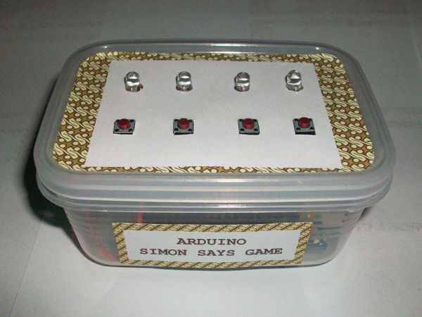
(1) Project enclosure (I’m using “Kitchen Ware” box)
– Breadboard
– Shrink tubing
– Jumper wire
– Rainbow wire (optional)
– Male header extended
– Blackhousing / female 1×1 header (optional)
[/box]
Tools:
– Soldering iron
– Solder
– Hot glue
– Mini drill
– Pliers
– Cutter
– Helping hands (if you don’t have it, you can build it from my helping hands instructable )
Step 2: Making the circuit on breadboard
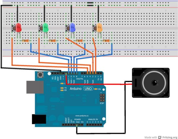
Let’s build it on breadboard first. First, lets put the components on a breadboard so we could see how it worked and how to fit it onto the perfboard. The circuit diagram was made with Fritzing.
Step 1
Put the buttons on breadboard. We’re gonna tie one lead of the buttons directly to ground. The other lead will be wired to the Arduino’s Digital pins 2, 3, 4, and 5.
Step 2
Put the LEDs above the buttons. Plug the LEDs in with the switches so the Cathode is on the same strip as the side of the button that is tied to ground. And arrange it so the Anode plugs in off to the side of the button.
Step 3
Add 330 Ohm resistor and put it inline with the Anode to the top section of the breadboard. Now we can connect a wire from the resistor to the Arduino.
Test everything out and make sure that you’re circuit is going to work before you start soldering.
Step 3: Write the code
The sketch was originally made by Robert Spann back in 2009. I just a beginner of Arduino so I got the sketch from mpilchfamily’s instructables . To give the game sound it using the Tone.h Library. You will get an error if you dont install the Tone library, downlod the tone.zip and put it in the adruino library folder. A file of the sketch and Tone Library is also attached.
You can go to How to Install a Library to learn it.
Step 4: Move to Perfboard
Step 1
Cut the perfboard about 7 cm x 5,5 cm.
Step 2
Arrange the component, I usually place all components in before starting to solder. But if you want to do soldering one by one, you can mark on the perfboard which legs of your component will be placed.
Step 3
Arrange the push buttons. (see image 1)
Step 4
Put LED, the cathode connect to the push button, the anode connect to the resistor. I’m using 330 Ohm resistor, because I want my LED no so bright. For the resistor, I put it backward on purposed for efficiency with the enclosure.(see image 2 and 3)
Step 5: Complete the circuit on perfboard
Step 1
Add a jumper wire for connect the push button with LED (cathode). (See image 1)
Step 2
Using a rainbow cable to connect the circuit with the Arduino. (we’re gonna make 2 packets cable, each packet consist of 4 cables)
– We need 4 cables, and 4 male header
– Strip the end of the cable, about 0,5 cm (see image 2)
– Put the wire / bend it around the male header (see image 3)
– Solder it together (see image 3)
– Make 2 packet of these. (see image 4)
Step 3
Solder the first packet cable with resistor. And solder the second packet cable with the push button. (See image 4)
Step 4
Add a ground leads, I made it from a quite long wire. and put the wire for connect to the ground of Arduino. (see image 5)
Step 5
Check the components once again before soldering.
For more detail: Arduino – Simple Simon Says Game