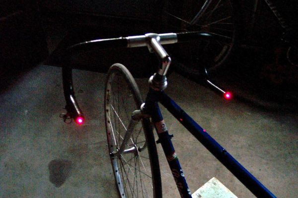
This project was inspired by a very cool kickstarter called Helios Bars. Essentially what this project does, is put an arduino, LEDs, and buttons into your bike handlebars. The LEDs can be used as turn signals, brake lights, or display ambient colors while riding. It’s fun, cheap, and a good introductory to LEDs and arduino. The coolest thing though is that the project can be completely enclosed in the handlebars and even waterproofed! This is because the Arduino Micro will fit inside handlebars with an inner diameter of 0.7 inches or greater! It is also a cheap project with a cost of around $30-$40 to buy everything. The best way I can explain it is by showing it, SO CHECK IT OUT BELOW!
Step 1: Parts List
[box color=”#985D00″ bg=”#FFF8CB” font=”verdana” fontsize=”14 ” radius=”20 ” border=”#985D12″ float=”right” head=”Major Components in Project” headbg=”#FFEB70″ headcolor=”#985D00″]
To modify your handlebars this project uses a ‘kit’, all the pieces of which can be bought at a place like Radioshack. It’s a fairly simple and cheap project, with few components.
Parts:
Arduino Micro – You could also use Arduino Uno or any others, but they would have to be externally mounted to the bike. If you have a choice, get the version of the Micro without headers.
2x Pushbuttons – I used 12mm ones seen in the picture, and they work awesome.
2x RGB LED’s – These need to be common anode to work with my code. I recommend 2, but the number is up to you. You should probably get more just in case.
Resistors – These are needed for the pushbuttons and the RGB LED’s, so they will be specific to what you use. I used four 2k ohm resistors.
Batteries – Anything 6V or greater works but I will discuss this a lot more in the ‘Custom Battery’ step.
Wire – Lots and preferably thin and flexible.
[/box]
Tools:
Soldering Iron
Drill
Metal Files
Additionally if you want to waterproof the bars be sure to get some sugru. More on this in Step 7.
Step 2: Basic Circuit
Circuit Description:
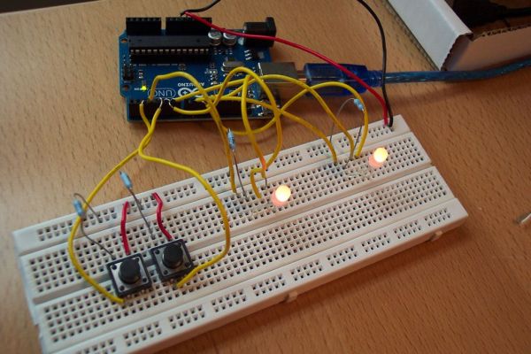
So the design of this project boils down to the schematic for the LEDs and the buttons in the pictures. It’s much easier to see the circuit from the pictures but I will describe it just to be safe. There are three things that need to be connected to the arduino: the LEDs, buttons, and battery. The LEDs are hooked up to 5V through a resistor (resistance value depends on your LED) and three signal wires. The buttons will have a 5V, ground (through a resistor, once again the resistance depends on your button), and signal wire. You will also need V-in and ground wires connecting your battery to the arduino. That’s the extent of the circuit! To keep things simple I used a central ground and 5V wire that ran the whole length of the bar so I could solder all the components onto them wherever they were needed (I used this ground wire to connect the battery as well).
Extra Info:
Once you have all your parts I recommend breadboarding your components into the circuit to do some testing and make sure the program runs properly. Note that the way to hook up your RGB LEDs may be different depending on what kind you have (I have common anode RGBs). I control the RGBs using the PWM pins on the arduino so be sure you hook up the LEDs to the exact same pins I do (you can use other PWM pins but you will have to modify the code). Once you have it set up then you are ready to test it with my program, or your own!
Step 3: Program
The arduino IDE for writing code and programming any arduino can be foundHERE. You can grab my program in the word file I have attached to this step and copy paste it into a new arduino sketch. Then, connect the arduino micro using a Micro B/USB cable to your computer and click the upload button on the arduino program. If you are having trouble uploading or don’t know how tryHERE or HERE.
NOTE: if you don’t have common anode RGB LEDs then you will have to modify my code. Try switching the values for the variables ‘off’ and ‘on’ and it should work.
Step 4: Soldering the Components
Laying Out Circuit:
When soldering your circuit make sure you leave a little extra wire length for the LEDs and arduino, for the buttons though, the wire distance between them must be EXACTLY the same as the distance between their mounting holes (or quite close). It is very difficult to push the wire together of it is too long. I can’t help you with exact lengths of wire because depending on LED placement, number of LEDs, handlebar shape, and button placement, the lengths of wire used change dramatically. I recommend pushing just one wire through certain sections of the bars to find exact lengths of wire. I planned on having the battery opposite the end of the handlebars with the arduino so you’ll also need to measure out lengths of wire the length of the handlebars for the ground and V-in wires.
Cleaning Up Wiring:
To keep the wiring clean I would twist certain sections together, such as the three signal wires for the LEDs or the 2 signal wires for the buttons. I then took these 4 or so braided wires and arranged them how they should be to attach to component and taped them all together every 6 inches or so. I also laid out all the components to keep myself from getting confused. This kept things as clean and organized as possible.
Soldering:
Next I soldered the wires to my components, leaving the arduino for last. Use plenty of solder to ensure strong, durable connections. After soldering make sure to wrap all exposed solder joints and metal with electrical tape or something similar to prevent accidental circuit changes/shorts.
Testing:
Double check your circuit schematic with mine and test to make sure it works before moving on.
NOTE: If your arduino micro has headers you may need to desolder them so they will fit inside the bike bars. An awesome guide for desoldering can be found HERE.
Step 5: Preparing the Handlebars
This step seems long but really you are only drilling holes in your handlebars and endcaps.
Removing Handlebars:
Take your handlebars off your bike by undoing the allen screw(s) holding them in place at the top of the fork. There are many possibly ways they could be attached so I’ll let you figure that out. Next, remove your handlebar grips/tape and brakes. After you have the bar completely off and bare, remove the end caps by prying with a screw driver. Next, use a marker and plot where you want to make holes for the LEDs and buttons. I placed the buttons 4 inches on either side of the center of the handlebars and the LEDs in the end caps.
Drilling Endcaps:
Now you will need to find two drill bits. One that is the size of the LED “bulb” and another the size of the button part of your pushbutton. First take your end caps and use a clamp to hold them in place. Fix your LED drill bit into your drill and make a hole clean through the center. Test to see if your LED is able to protrude from the outside end so will be visible when mounted. If not widen the hole by wiggling the drill bit or trying a larger bit. Repeat for the other LED.
Drilling Handlebars:
I recommend putting the bars in a vice. On the spots you’ve marked on your handlebar, use a hammer to pound a nail to make a small mark that the drill bit can grab. Then fix your button drill bit and drill each of the holes. You will also need to make another hole on the back part of the handlebar for each hole you just drilled (so you will have a hole going completely through both sides of the bar). This allows you to push from the back of the button and stick something in to keep the button pressed up against the handlebar so it can be clicked without falling back into the bar. I recommend doing 4 holes in the same spot (2 holes going completely through both sides of the bar). This is because it is extremely difficult to twist a button so it can be pushed through the holes you have drilled.
Finishing Touches:
Use a metal file to smooth the holes drilled in your handlebars. If you have a de-burring tool or a small file, then use those to smooth the inside of the holes as well.
For more detail: Bike Turn Signal & Brake Light Handlebars