I’m not usually one to revisit a project after I’ve finished it, but I made an exception because the problems with the original design were making this device unpleasant to use. For those of you just now viewing this project, it is the second iteration of an iPod information screen I made for my girlfriend a little over a year ago (seehttp://www.instructables.com/id/iPod-Information-Screen/). While she liked the first iteration, it left much to be desired in terms of functionality and appearance. This iteration addresses some of the biggest issues and makes for a better and more pleasant to use device.
This has been tested and works with the following iDevices. And I suspect it will work with any earlier generations also:
- iPod Touch 1st, 3rd, 4th generation
- iPhone 3GS
A quick introduction to what exactly this is:
My girlfriend, a huge music buff, asked me to come up with a better way for her to look at the track information of the current song playing on her iPod touch while she was using it in the car. Those of you that have or have had an iPod touch know that it’s not the easiest thing to read while driving. To see the song information you have to double tap the home button and then still the text is extremely small. Also, controlling playback is difficult as the iPod touch has no tactile buttons so it requires the user to look at the screen to find the location of the soft buttons.
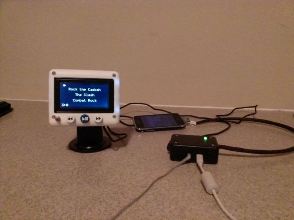
My solution was to construct a device that would interface with the iPod and take the song information and then display it on a screen somewhere within easy view of the driver. After quite a bit of work and research I finally arrived at the product you see here. My iPod information screen displays the song title, artist, album, song time, and play/pause symbol. It provides skip back, skip forward, and play/pause playback control as well as charges the iPod.
Step 1: New Design Considerations
For me, updating this project was a great study in design. I learned a lot not only about how to make this better, but also knowledge I can apply to future projects. In this step I’m going to go through major design goals and my reasoning behind them.
1. Make Main Unit Smaller
The main unit is the assembly that houses the screen, buttons, and Arduino. The original design used female headers that added significant thickness to the assembly and the board layout made the the assembly unnecessarily tall.
2. Better Main Unit Enclosure Aesthetics
I’ll admit it, the first iteration of this project was ugly. The black box was unattractive and the holes had uneven edges and weren’t the right size. Also, I had an old windshield suction cup mount that I hacked together something to make it stay on the windshield. It involved a lot of velcro and didn’t work very well. This time I wanted to make sure the unit attached directly to the mount.
3. Power Switch
The first iteration had no power switch. You turned it on and off by plugging and unplugging the USB cable that provided power. This is a hassle to a user who wishes to leave the device plugged up, yet still wants to turn it off.
4. Better Connection to iPod
The iPod connector breakout I used originally was large and it was difficult to make look nice with all the wires going to it. Another problem was that all the wires I used to connect the connector to the interface board were solid core and very rigid. Wrapping them in electrical take was another mistake. It was hard to put the iPod where you wanted it.
Note: A lot of people have mentioned that some sort of volume control would be good to add. As it turns out when the iPod is controlled through the method used in this instructable, volume control is disabled. I suspect this is because this mode is meant to be used with some other device controlling all playback functionality remotely and so volume would be controlled with the device. In this case, volume is controlled with the car stereo’s volume control.
Step 2: The Research
This is a necessary first step to any project. The following is taken from the original Instructable so that you don’t have to find that one to have access to these resources.
The first step in making this device was to find out if it was even possible. I had never even really given interfacing with an iPod much thought before this and I had no idea if protocols publicly existed to do so.
One of the first websites I came across when researching was a Cornell senior design website that detailed the development of an iPod dock that took and sent commands to an iPod. The site,https://courses.cit.cornell.edu/ee476/FinalProjects/s2007/awr8_asl45/awr8_asl45/index.html, was very helpful in detailing the necessary connections, but most importantly it showed that this was in deed possible to do.
I came across several more resources, and then stumbled upon my primary resource. I found David Findlay’s blog,http://davidfindlay.org/weblog/files/2009_09_07_ipod_remote.php, and on it he talked about his development of an iPod remote and an Arduino library that handled all the iPod interfacing in a very simple way. This is the library I used in my project.
I also found this website useful outlining the Apple Accessory Protocol,https://nuxx.net/wiki/Apple_Accessory_Protocol. It’s not really necessary to understand as David’s library handles this behind the scenes, but I thought it was good to know and it may be useful for other applications.
Step 3: Components and Parts
[box color=”#985D00″ bg=”#FFF8CB” font=”verdana” fontsize=”14 ” radius=”20 ” border=”#985D12″ float=”right” head=”Major Components in Project” headbg=”#FFEB70″ headcolor=”#985D00″]
Electronics
- Arduino Pro Mini (I did some prototyping with an UNO)
- PodBreakout Mini
- Push Buttons
- Graphical LCD (I’m using the MONOCHRON from Adafruit)
- 10k Contrast Potentiometer
- USB Mini Connector
- 3.5mm Audio Jack
- Rocker Switch
- Green LED
- 150k Ohm Resistor
- 100 Ohm Resistor
- 1k Ohm Resistor (3x)
- 1M Ohm Resistor (2x)
- 33k Ohm Resistor (2x)
- 22k Ohm Resistor
- 47k Ohm Resistor
- Male Headers
- Wire[/box]
I got almost everything from Sparkfun.com.
Enclosures
The main unit enclosure I had 3-D printed by shapeways.com, more on that later. The interface enclosure in just a small project box from Radio shack.
Printed Circuit Boards
There are three boards in total. I had one manufactured by Seeed Studio and the other two I etched myself. I will talk more about these later.
Tools
You’ll need basic electronic tools like wire stripper, cutter, plyers, soldering iron, etc.
Step 4: The Hardware
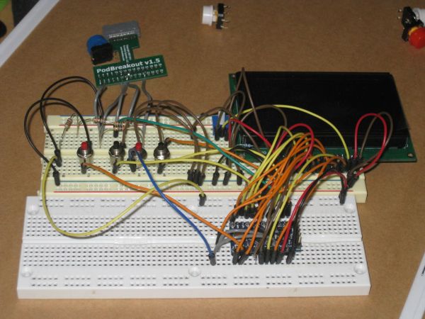
Since I’m using an Arduino the circuit is simplified as all the components to make the microcontroller run are on the Arduino board. The remaining connections are just attaching wires and resistors. The pinouts of the iPod connector is, of course, very important to know and can be found here:http://pinouts.ru/PortableDevices/ipod.shtml.
The connections that need to be made are detailed next to each pin on the website above. Also, the websites I’ve listed earlier in this Instructable talk about them too. I’m also going to touch on it. The Fritzing drawing should help clarify any confusion with the EagleCAD schematics shown.
Main
The LCD display uses the KS0108 chip popular to a lot of LCDs. There is a library for Arduino called GLCD. This takes most of the pins from the Arduino. For proper connections I’ll refer you to the documentation that comes with the library. A link to the library will be provided in the next step.
The serial transmit TX and receive RX, pins 1 and 0 respectively, go to the serial lines of the iPod. Be sure TX of the Arduino goes to RX of the iPod and vice-versa. That is, Arduino pin 1 to iPod connector pin 18 and Arduino pin 0 to iPod connector pin 19. Since the iPod operates at about 3V and the Arduino operates at 5V we need to use a voltage divider on the Arduino’s transmit line. That’s what the 1k Ohm resistors are for. Technically, I should be using a level shifter, but I found that it worked fine without it and the Arduino has no problem with receiving the incoming 3V data.
The remaining connections are for buttons.
Interface
Pin 21 of the iPod connector will be connected to ground through a 500k Ohm resistor, or in my case I used two 1M Ohm resistors in parallel. Connector pins 25 and 27 control how the iPod charges. If we put 2.8V on pin 25 and 2.0v on pin 27 we can get the iPod to draw about 1A and charge the battery. The is accomplished by simple voltage division as can be seen in the second schematic.
Other
All other connections are just straight connections. See the schematic and pinouts.
For more detail: IPod Information Screen Rev. 2