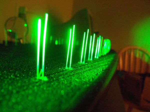
This mod uses a custom designed encoder on one of the wheels to track where the longboard is on the ground and light up the LEDs so that the light pattern remains stationary on the ground as the board moves over it.
![]()
To make doing this instructable as easy to understand as possible, you will need to know how it works up front. There are rare earth magnets on one of the wheels. As the wheel turns, there is a sensor that reads those magnets and tracks how fast the ground is moving under the board. That sensor reports to a microcontroller that turns LED’s on/off in sequence so that the light appears to be stationary as the board moves over it. The faster you go, the faster the LED’s shift and likewise, the slower you go, the slower they shift.
Step 1: Materials and Tools
[box color=”#985D00″ bg=”#FFF8CB” font=”verdana” fontsize=”14 ” radius=”20 ” border=”#985D12″ float=”right” head=”Major Components in Project” headbg=”#FFEB70″ headcolor=”#985D00″]
This project can get pricey if you don’t have some of these things already. Know that before you get started 🙂
Materials:
~Longboard (or skateboard)
~Arduino Mega (or pin equivalent)
~60 “super bright” LEDs
~60 100 Ω resistors
~1 10K Ω resistor
~1 latching Hall effect sensor
~150 feet of 22AWG solid wire
~2 meters of heat shrink (3/32″ dia)
~project box (one that will fit your arduino)
~cable ties (aka zip ties)
~cable tie anchors
~solder
~epoxy (5 minute works well)
~plexiglass
~1″ wide stainless steel strap
~painters tape (wide and green works best)
~rare earth magnets
~velcro
~9V batteries (rechargeable is smart)
~9V battery clips
Tools:
~Drill press and hand drill
~13/64″ drill bit
~1/4″ drill bit with stop
~carpenter’s square (a ruler will work too)
~soldering iron
~tweezers
~3rd hand
~soldering torch or lighter
~wire cutters
~wire strippers
Optional:
~sand paper
~wood stain
~polyurethane spray
Oh, and you will need A LOT of time! This isn’t a 1 weekend project ;)[/box]
Step 2: Drill your holes
You should read about how this project works on the first page. If you don’t, you may get confused as to why you are doing some of these steps.
Unfortunately I don’t have pictures of me doing the prep work and the first set of holes. I did it at work and I signed a contract that prohibits me from filming there (its a robotics company).
Prep work:
1) You will first want to find the circumference of your wheel. The rest of this project heavily depends on this number. My wheel happened to be almost exactly 8 inches around. If you have very worn down wheels, you should invest in new ones before starting this.
2) Divide the circumference by 8 or another even number so that your answer comes out to around 1″. It must be an even number for the magnetic sensor to read the magnets properly. Remember the number you divided by as this will be the number of magnets you will use in a later portion of this project.
3) Cover the edges of your board with wide, green masking tape.
Drilling:
4) Mark out your holes with the spacing you found in step 2 and about an inch away from the side of the board. For my longboard, that happened to be a hole every inch down the length of the board and an inch from the side. I had 29 holes on each side. You can see the finished product below.
5) Drill your holes carefully with a 13/64″ bit and a drill press. Using a drill press is important because it allows you make near perfect holes so your light shines straight and your LED doesn’t need to be glued in.
Countersink:
6) Countersink the tops of your holes with a 1/4″ drill bit and a stop. My stop was a fancy one, but you can wrap tape around your drill bit so that only the tip sticks about 1/4″ out (see pic). The idea is to drill out just enough so that the LED’s tip will sit flush with the bottom of the board. If it sticks out, you can break the LED’s easily if you run over something (ie a curb). If it is too far it, some of your light won’t make it out of the hole.
Step 3: Insert LED’s and Wiring Prep
Wire tie prep
1) Mount your cable tie anchors on the underside of your board in even intervals as you see in the picture.
LEDS:
2) Insert the LEDs into the holes. I inserted the LED’s with the anode (long) pointing towards the outside of the board and the cathode (short) pointing inwards toward the middle of the board. There is a picture of this below. This is important in the next step. You might want to use a pencil or a screw driver to push these all the way in so that you don’t damage the leads accidentally.
3) Bend your leads so that the cathodes (long) stick out of the board’s side and the anodes (short) all point towards the nose of your board. Later, we will be soldering all of the anodes together and then wires to the cathodes. Be careful not to let these rotate while you are bending them down so that they don’t rotate and short the LED. Again, a picture below.
Step 4: Make your Magnetic Encoder
The heart of this lies in the custom magnetic encoder that we are about to make. Even if you breeze through the rest of this project, take a little time to do this right.
You will need your epoxy, sandpaper (80g), magnets, a sharpie, and a protractor (optional). I originally used super glue to do this, but I found that it doesn’t hold very well to the vibrations that come with riding the longboard.
Prep work:
1) Mark either north or south pole of ALL the magnets with the sharpie. It doesn’t matter which, but you do this by stacking the magnets together and marking the same side of all of them. This helps you keep track of what side is what, which is ESSENTIAL TO MAKING THIS WORK RIGHT.
2) Mark out where the magnets are going to go. You want them to be about half way between the center and the outside of the wheel. You will need to mark out the same number of spots as you have magnets, using the protractor to get them even if needed.
3) Lightly sand the magnets and the inside of your wheel. This gives your epoxy a little something extra to cling on to when the wheel is spinning super fast and vibrating violently, you should take what you can get.
Putting the magnets on:
4) Choose to start with one pole or the other and epoxy a magnet in every other spot. When that sets, reverse the polarity so that the other pole is facing upwards for the remaining magnets. Going around the wheel, they should go N, S, N, S, N, S….ect. You can test this by holding a magnet to each one so that the pattern is attract, repel, attract, repel…ect.
Note: Due to how this project is coded, t isn’t completely necessary for the magnets to be perfectly in the right place, but you should get them as close as possible.
Step 5: Wire em up!
This is the tedious part….you will be putting in around 60 wires, soldering about 200 splices, using around 100 pieces of heat shrink, strip off 250 wire ends, and will get burned by the soldering iron at least twice 🙂
You will need: solder, wire, soldering iron, lighter/torch, zip ties, wire cutters/strippers, 100 Ω resistors, and a great deal of time.
Wiring:
1) Cut around 60 5″ wires and strip the edge off of each one.
2) Put zip ties through all of the anchors and tighten them slightly so that you have big, open loops.
2) Solder the stripped end to each LED. Use a third hand if you are unsteady or tweezers if you aren’t fast enough to not get burned by the hot wire.
3) Bend the wires over the side of the board and run them through a zip tie loop so that they all point towards the front of the board.
4) Cut wires to an appropriate length after soldering them and strip off the other end.
5) Solder a 100 Ω resistor to each wire.
6) Cut a length of wire that goes from the end of each resistor to about 8 inches past the nose of your longboard. Strip both ends, run it through the zip ties, and solder one of them to the resistor. Be certain to put a piece of heat shrink over the solder joint and LED to make sure you don’t light up any LED except the one you want. When in doubt, cut your wires extra long…it is much easier to clip them down then try to make them longer with splices.
7) Bridge all of the anodes. You can do this by soldering them together or with short wires. I did both for redundancy and reliability.
Step 6: Getting the wires ready
You will need: double sided mounting tape, masking tape, a sharpie, your project box+arduino combo, wire cutters/strippers, a power supply (such as a USB chord or wall wart).
Mount your arduino:
1) This is pretty simple. Pick a spot that you’d like your microcontroller, put double sided mounting tape on the underside of your box, and stick it on. If you are sure that you know where everything is going, you can go ahead and epoxy it on. The reason you need to put your arduino on you board is to make sure your LED wires are long enough and that you like where it’s at.
Mark your I/O
2) Put tape down the top of your board and mark one side with even numbers starting with 0 and the other side with odd numbers starting with 1, both of which start at the nose end of your longboard. These will be your pin numbers.
3) Plug your arduino into a computer or other power supply.
4) Run your ground wire (common anode), to the ground port on your arduino.
5) Take each wire and plug it into the 5V port, watch which numbered LED lights up, write it on a piece of tape, and put it on the end of the wire.
For more detail: Ground Tracking LED Longboard Mod