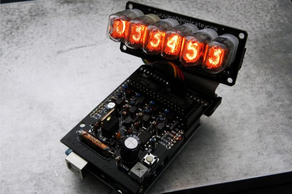
www.ArduiNIX.com presents: ArduiNIX Nixie driver shield assembly
The ArduiNIX shield is a user programmable platform for driving multiplexed Nixie tube or other high voltage displays**. The ArduiNIX is open source hardware
 Welcome to the assembly portion of the site. Here we will take you step by step through the build process of your ArduiNIX kit. First, make sure you have your parts all accounted for!
Included in your driver shield kit should be the following parts. This is the most current, up to date parts list for the ArduiNIX.
- (1X) ANX_Board
- (1X) Damper Diode 1.0 Amp 400 Volt BYT01-400 511-BYT01-400 @ D1
- (1X) 100uH 1 Amp RFI Suppression Coil 434-11-101M @ L1
- (1X) 25 Volt 470 uF Capacitor 647-UVZ1E471MPD @ C2
- (1X) 350 Volt 1 uF Capacitor 647-UVR2V010MED @ C1
- (1X) 500V 5.6 pF NPO Capacitor 140-500N2-5R6D-RC @ C3
- (1X) 500V 47pF SL Capacitor 140-500S5-470K-RC @ C4
- (1X) IRF730 400V 5.5 Amp Single-Gate MOSFET 844-IRF730APBF @ Q10
- (1X) 1/4″ Squ 1K 10% Single Turn Trimmer 858-25PR1KLF @ R19
- (1X) 6X6 FLAT 4.3mm BTN Tactile Switch 653-B3F-1000 @ S1
- (1X) General Purp Single NE555N Timer IC 511-NE555N @ IC1
- (5X) 1/4watt 33Kohms 5% Metal Film Resistors 71-CCF07-J-33K @ R1-R5
- (4X) 1/4watt 100Kohms 5% Metal Film Resistors 71-CCF07-J-100K @ R6-R9
- (4X) 1/4W 470K ohm 1% Metal Film Resistors 660-MF1/4DCT52R4703F @ R10-R13
- (2X) 1/4watt 1Kohms 5% Metal Film Resistors 71-CCF07-J-1K @ R14, R15
- (1X) 1/4watt 10Kohms 5% Metal Film Resistors 71-CCF07-J-10K @ R16
- (1X) 1/4watt 220Kohms 5% Metal Film Resistor 71-CCF07-J-220K @ R17
- (1X) 1/4watt 470ohms 5% Metal Film Resistor 71-CCF07-J-470 @ R18
- (4X) PNP MPSA92 Small Signal Transistor 512-MPSA92 @ Q6-Q9
- (5X) NPN MPSA42 Small Signal Transistor 512-MPSA42 @ Q1-Q5
- (2X) Nixie Driver IC – SN74141 *OR* Equivalent @ IC2, IC3
- (1X) 40P .100″ Pin Strip Headers 517-6111TG Pinrails
Step 1: Lay out your parts
Lets lay out your parts in an easily accessable and organized manner. We don’t supply the solder station, but it would be very handy if you had something similar to assemble your kit with. My solder station is a large metal plate with a panavise and third hand alligator clip helper bolted to it. One end of my third hand helper is modded to hold my solder reel.
Step 2: 1.0 Amp 600 Volt Fast Recovery Rectifier Diode @ position D1
D1 is the Fast Recovery Rectifier Diode. Make sure it goes in correctly, it may only be installed one direction. The band on one end shows you which side is the positive side.
The diode we supply may either be a 400 or 600 volt diode. Either will work.
Use something handy to pull the diode up snug to the board, preferably so your hands are free to solder the leads in.
This is how D1 should look once it’s installed correctly.
Step 3: 100uH 1A Coil @ position L1
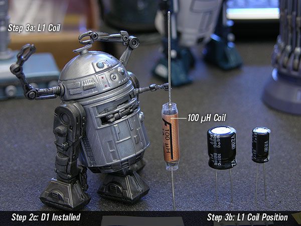
This little fellow is going to be helping us pick the correct parts to place on each step. Here he is holding up the 100uH Coil.
The coil is one of the main components that allows us to take 9 volts up to 180. It can be installed either direction, so don’t worry about polarity.
How nice, the diode and coil are going to be best friends.
Step 4: 25Volt 470uF Capacitor @ position C2
Thanks robot buddy. That’s the large Capacitor we need next. C2 is a polarized 25Volt 470 uF Capacitor. The stripe on the side with the “-” signs in a row show you the negative side. This one has to be installed the proper way!
Make sure the negative side of C2 is not inserted into the positive hole on the board.
It should look like this when it’s installed correctly.
Step 5: 350 Volt 1 uF Capacitor @ position C1
Yessir, C1 is the smaller of the two polarized capacitors. C1 is a 350 Volt 1 uF Cap.
Like C2, C1 must be oriented the correct way on the board.
Step 6: 500V 5.6 pF NPO Capacitor @ position C3
Now we move on to C3. C3 is a component which varies from kit to kit. This capacitor controls the voltage range on your unit. The cap we supply may vary from the photo.
Again, C3 is a component which varies from kit to kit. This capacitor controls the voltage range on your unit. The cap we supply may vary from the photo above. As we make slight modifications and improvements to the kit, this component stands to vary the most, so don’t worry if your cap doesn’t look exactly like this.
The current rev of this part is a 500V 5.6 pF NPO Capacitor.
Step 7: 500V 47pF SL Capacitor @ position C4
Now we have C4. This cap works with C3 to control the voltage range. C4 is a500volt 47pF capacitor.
C4 may be installed either direction, polarity is not important with C3 and C4.
Step 8: IRF730 400V 5.5 Amp Single-Gate MOSFET @ position Q10
Hey fellow, you’re a swell guy for showing the folks the IRF 730 MOSFET Transistor!
This power transistor must be installed correctly, with the metal tab aligned over the solid white stripe at position Q10 on the board.
Using a third hand to tug slightly up on the leads while soldering makes for a great installation.
For mor detail: Arduino Powered Nixie Tubes: ArduiNIX Nixie driver shield assembly