We are a generation that love sound and light – can’t do without them really. Our most preferred time of day is night, or what we would call evening. We are particularly well acquainted with technology; doesn’t hurt these days. Our prerequisite for everything is that it be ‘cool’. Put it all together and in a stroke of brilliance, and a little help from our friend the internet, we have the ideal solution – a laser harp.
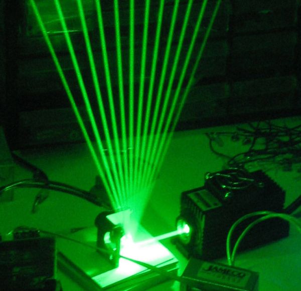
A laser harp, what on earth is that? Sounds kind of fancy doesn’t it? Well, it is basically what it says it is. The laser harp is an electronic instrument where a motor, a light sensor, a microprocessor Arduino, and, I’m sure you’ve guessed, a laser collaborate to produce beams, each representing a note (we will elaborate for those who care to read on). This harp though doesn’t have a frame: its strings stretch out infinitely into space – we know no boundaries.
Our inspiration was a video we had watched online and found rather fascinating. Apart from the fact that the prospect of creating it without too much expenditure, mental or monetary, was exciting, it seemed a project providing scope for learning in different areas, especially since we wanted to present it as a complete product. Part research, part reverse engineering led us to figure out its functioning. Admittedly, we have not contributed any addition to the original creation, but to achieve it was in itself gratifying. And there’s always room for originality and improvement in the future.
If you like our instructable please vote for it at the top right corner of the page!
For making this laser harp you will require basic soldering skills, and some experience working with the arduino.
Word of caution: Lasers are very harmful for the eyes, make sure you wear appropriate eye protection.
Our Video will be ready in another 12 hours! Do come back and check it out!
Step 1: Overview of the harp
The basic outline of the harp:
How the beam is created:
How the harp knows which beam has been cut:
Step 2: Parts..
[box color=”#985D00″ bg=”#FFF8CB” font=”verdana” fontsize=”14 ” radius=”20 ” border=”#985D12″ float=”right” head=”Major Components in Project” headbg=”#FFEB70″ headcolor=”#985D00″]
Here you will find the complete parts list you need and some info to create the project yourself:
Main parts
Stepper motor:
A stepper motor is an electromagnetic device which converts electrical pulses into extremely
small mechanical movements (steps). Its shaft rotates by taking these steps when the
electrical command pulses are applied in the required order, and its speed and direction
depend on their frequency and sequence.
A stepper motor has the following attributes:
•Number of steps per rotation
•Torque (the weight it can bear)
•Step angle accuracy
By manipulating the control pulses, you can make the stepper motor carry out different
function such as taking half steps (e.g. 400/rotation instead of 200).
For our project we will be operating in full step mode.
Arduino:
Arduino is basically a small computer which reads an input, interprets it, and sends an output, where the input,output, and interpretation can be practically anything (in the electronic field!).
It is a magical board which makes your electronic dreams come alive.
Bread board:
The more powerful your laser, the more effective your harp will be, ours was rated at: <50 mW
And as for color, we’ve chosen green, since it was completely safe for the skin at that power rating.[/box]
ULN2003
2N2222 TRANSISTOR
LDR Light Sensor
MIDI jack
MIDI to usb adapter. (This parts is optional, it has been explained in the MIDI section)
5k TRIMPOT
Small Mirror
Green Laser Safety Goggles
White Gloves
Power Supply, 12V DC 2A (This parts depends completely on your stepper motor, go by its rated power)
Soldering iron
Materials for the enclosureTotal estimated cost: 90 – 100 $
Step 3: Wiring guide for steppers
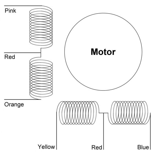
It is essential to send the command pulses in the right order. A step motor will
typically have six wires. Here is a quick guide to identify which is which.
With the help of a multimeter, we first isolate two groups of three wires, forming
two coils, by checking the continuity function, ensuring that the circuit
is complete.
Next we identify the middle wire of each coil. Using the resistivity function, check
the resistance between all combinations of pairs of wires. The resistance between
two ends will be twice that between the middle wire and either end.
If your stepper motor does not have 6 wires, here is a wonderful resource to help you out:
Step 4: Wiring it all together:
In the first image you will see the fritzing diagram for the harp. And in the following images you will see the step by step process for building the circuit on your breadboard.
We begin by placing the ULN2003, keeping in mind the direction of the little notch on the chip.
We then wire the stepper motor’s signal pins into the chips OUT pins and the common wire into the chip COM pin.
In this step we connect to the arduino via the chips IN pins and we connect our power supply to the chip.
For the next steps we add the transistor, the laser, the LDR and the MIDI jack.
Refer to the fritzing diagram (first image) if anything is unclear.
Your circuit is now ready!
For more detail: Frameless Laser Harp