The Luna Mod Looper, basically lets you record a sequence using a potentiometer to control the pitch of the note, and then play it back and add affects. Ever since I saw videos of the Luna Mod being played, I wanted to build my own. However, the project required a picaxe microcontroller, which I have none of, and have no experience with. Fortunately, after a few web searches I came across some code for a Luna Mod for the attiny45 or the arduino. this project requires much less hardware than the original project, and allows you to add much more affects (although for this I chose to just keep it simple and add later) because the arduino still has a lot of unused pins, and a lot of room for more complex code. Along with being pretty easy to build, this is very fun to play with, and works very well.
Step 1: What you will need
You will need:
-an arduino uno / clone or an ATtiny 45 and a way to program it (i.e. a programming shield for the arduino)
-two pontentiometers (value does not really matter)
-a buttonswitch (the original project called for momentary but I used a push on push off switch so I wouldn’t have to hold it)
-two LEDs and cases
-resistors to go with the LEDs (i.e 220 ohm)
-spst toggle switch
-1/8″ audio jack
-DC female power jack
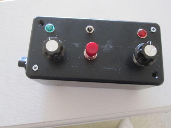
-project box
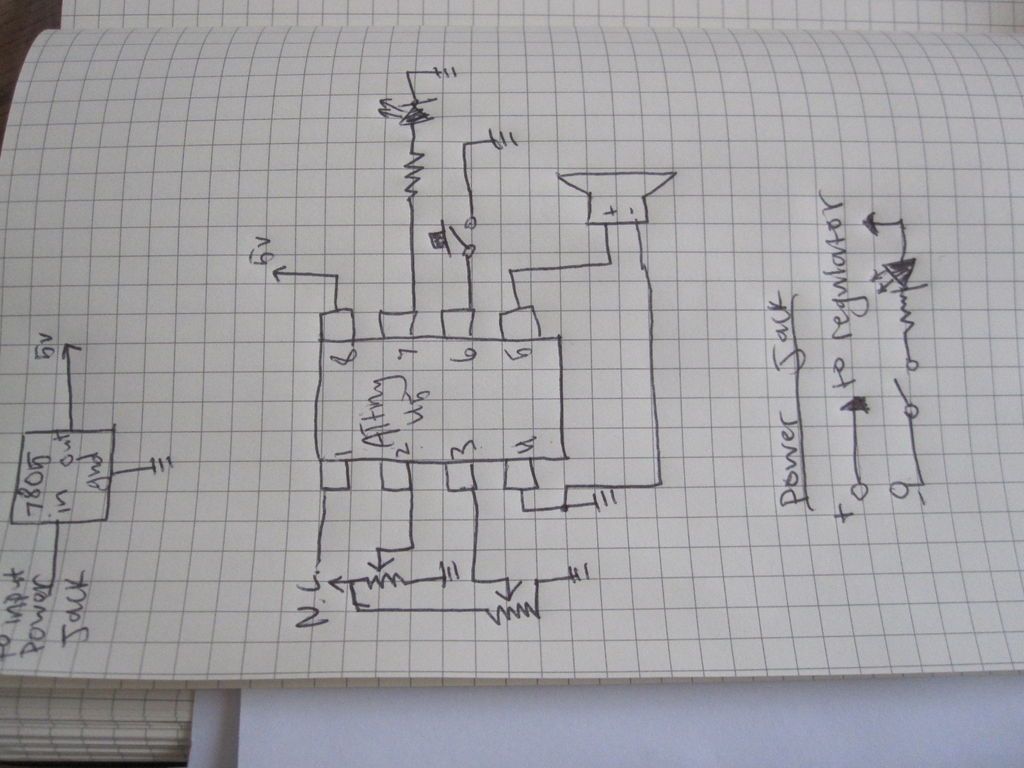
Step 2: The circuit
There is nothing special about this circuit. Using the ATtiny45 you would need to connect everything to the right pins, and connect the 7805 correctly, but if you are using the arduino you probably won’t even need a board, sense all the components are for interface. I simply connected all my parts to header pins and attached the headers to the female headers on the arduino board, this way I could easily remove everything when I want to use my arduino for something else in the future. construction of the circuit should be pretty strait forward as you simple connect everything to the right pin, with no need of extra hardware.
on the arduino, the frequency pot goes to A0, the tempo pot goes to A1, the record button goes to pin 9, the tempo LED goes to pin 10 and the speaker goes to pin 11.
On the ATtiny 45, you will have to choose what pins everything will go to since the sketch is setup for the arduino and you will need to change the pins. be sure to put the speaker and button on either pins 0 or 1 (5 or 6 on the chip).
If you use the arduino to do this, there are a ton of unused pins and plenty of space in the code for you to add your own personalized affects. Maybe add a glide button, or maybe even an LFO pot. There are practically no limits. Even with the ATtiny45 you could replace the tempo LED with a button/pot and add some extra affects.
Step 3: Program the arduino
*
* LunaMod for Arduino & Attiny45
* Remix by Rob Miles
* Tacoma, WA August 8th 2011
*
* I saw the original project in Make vol. 26
* by Brian McNamara
* Brian’s was running on a PicAxe and I only have attiny45s so…….
*
* The freqout section where the real magic happens is from Paul Badger’s synth code on the main Arduino site
*
* I kept this pretty straight forward but with an Arduino this could get a lot more complicated if you like
* Even on an attiny45 if you use you add a button to the led pin you coud sneak in more effects
*
*/
#define frequencyPot 0 //frequency pot tied to pin 15 which is A1
#define tempoPot 1 //tempo pot tied to pin 16 which is A2
#define buttonPin 9 //programming button tied to pin 17 which is A3
#define ledPin 10 //status led tied to pin 18 which is A4
#define speakerPin 11 //speaker or output pin 19 whish is A5
//if you use a speaker it should be at least a 16 ohm speaker an should have a
//resistor, maybe 200ohm to 1K ohm, between the negative lead and ground.
//a potentiometer would be even better.
int currentStep = 0; //this is just to track which tone in memory we are currently playing
-two pontentiometers (value does not really matter)
-a buttonswitch (the original project called for momentary but I used a push on push off switch so I wouldn’t have to hold it)
-two LEDs and cases
-resistors to go with the LEDs (i.e 220 ohm)
-spst toggle switch
-1/8″ audio jack
-DC female power jack
-project box[/box]