The Birth of RoboDolly
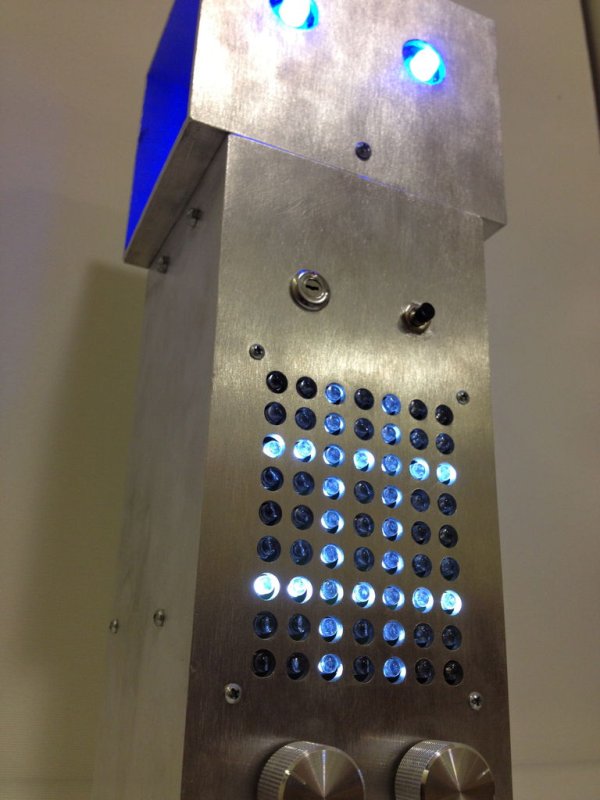
The conception of the RoboDolly can be traced back to my senior year of high school. This aluminum ornament evolved from housing a few flashing lights to displaying a fully handmade LED matrix. The final product was awarded to my robotics programming mentor; it now sits on his desk and gleams at his envious co-workers.
Versions
The following will provide a step-by-step guide of the RoboDolly’s creation. As this robot served primarily as a learning experience, I was involved in each aspect of its design and creation: body, electronics, and software. The first version of the robot, which was gifted away, was completely hand-wired. It can be distinguished in the photos by its spaghetti-like wiring, use of perfboard, and black knobs. The second version was made entirely with PCBs, which greatly reduced the amount of wiring. This instructable will focus on the latter model, although photos of the original will be provided for reference.
Files
Attached, you will find all the necessary files. They are all neatly zipped into ‘RoboDolly_files.zip’. The enclosed files will be referenced hereafter by filename.
[box color=”#985D00″ bg=”#FFF8CB” font=”verdana” fontsize=”14 ” radius=”20 ” border=”#985D12″ float=”right” head=”Major Components in Project” headbg=”#FFEB70″ headcolor=”#985D00″]
Parts
In ‘parts.xlsx’, you will find a list of all parts necessary for the project. Although the calculated bottom line sums to $103.80, the final cost is likely to be far higher. Most of the parts listed cannot be purchased individually; instead, they are sold by the foot or in a pack. Also, all of the suppliers mentioned are online retailers who charge shipping fees. The cost of my latest version totaled roughly $180. You may make substitutions for certain parts, but this should be done with extreme caution. For example, the power connector mounted to the rear of the robot must be constructed of plastic: a metal jack would ground the electronics against the body of the robot, which would cause the device to appear dead. (Of course, I found this out the hard way.)[/box]
Step 1: Body
Cutting the Body and Head
The body and head are constructed solely out of 4″ square aluminium tubes. It is this simplicity that provides the RoboDolly with his unwavering elegance. The body is a 10″ vertical length of this material, and a 5″ horizontal piece comprises the head. This is shown in the rendering below. These parts were cut with a band saw and the edges were thoroughly filed. Clean edges and dull corners are especially important for a project such as this. Since the final product is going to be used as decoration in a home or office, sharp edges are likely to cause injury. Any remaining burs, on the other hand, may damage electronics in or around the robot.
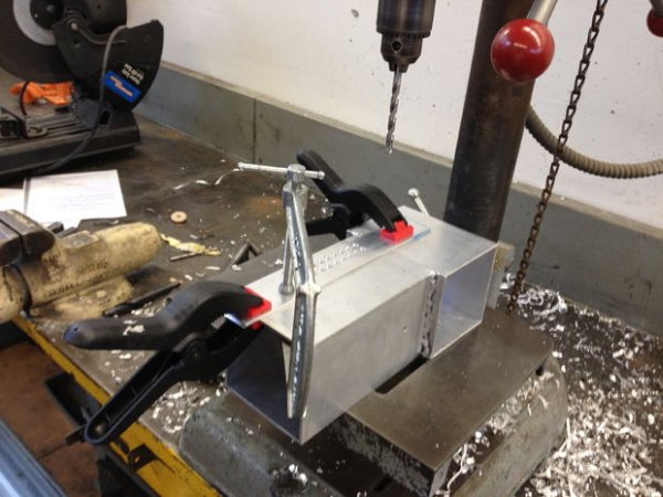
Drilling the Matrix
Drilling the holes for the LED display is no simple feat. The mill I was using had a broken cross-sliding vise and therefore only allowed for a few inches of motion. I was forced to use the mill only to create a template. This template included two columns of the grid (9 X 2) with 0.4″ spacing between the holes. Ideally, a template should be made out of a harder material than the piece being drilled, but a piece of scrap aluminum was enough for a single robot. After the template is created, print ‘matrix_template.pdf’ and carefully follow the instructions in the file. Align the paper template with the edges of the body and position it to the proper height, pulling the paper taut over the metal as you secure the pattern with packaging tape.
Clamp the metal 2-row template over the first two columns of dots, aligning painstakingly. After drilling these two rows on a drill press, move the template over a column at a time, aligning the previously drilled holes to the first line of the template. Ensure that this is as exact as possible, as mistakes will be quantified with each successive column. If you are not careful, the grid can melt into a rhombus. (An alternative method is to drill directly into the paper template without a metal guide; however, experienced machinists will note that this will allow the tip of the drill bit to shift and miss the dot.) Clean off any burs that may have developed on the inner edge of the holes, perhaps giving the inside a nice filing. I recommend practicing first on a piece of scrap metal. I was able to eliminate burs by changing the speed of the drill and the pressure I applied while boring into the metal.
Component Holes
The easiest way to drill holes for the components is to take a look at their datasheets. The diameter for panel mount components is often stated in these documents, and a slightly larger bit will likely suit the task. For the switches, potentiometers, and DC jack, it is best to seat these components in scrap metal before drilling into the body. For the circuit boards, it is best to lay the unpopulated boards face-down on the outside of the robot and mark the screw holes. Make sure to keep clearances in mind, and perform a dry run of installing components even before creating mounting holes.
For the head, you will need to drill a hole in the center of bottom side; the ribbon cables from the eyes will pass through this hole. In the front of the face, drill holes far larger than the 10mm LEDs. However, the LED mounting holes in the plexiglass itself should produce a tight fit. Two additional holes should be placed through both layers — head aluminum and plexiglass — for attaching the two materials. The LEDs will be fixed to the plexiglass with epoxy after wiring.
For more detail: RoboDolly