This project is designed to help you construct some relay boxes for controlling power from your wall socket using an arduino or microcontroller. The inspiration for writing an instructable came when I decided to build some relay boxes for my personal Garduino project. For safety concerns I started designing my own relay circuit and outlet until I came across SparkFun’s article “Controlling Big, Mean Devices”.
I decided to abandon my own plans mainly due to time and cost and ordered the parts from SparkFun. What follows is essentially the same information you’ll find on their guide but with a few of my own notes. I hope that you find my insights helpful and it will get your project off the ground without a hitch.
Step 1: Parts and Safety
The great thing about this project is that there aren’t a lot of parts that you need to get started. You probably have most of the parts lying around your junk box and the rest you can order directly from SparkFun or your favorite supplier. I’ve made a list of parts available on my wiki. SparkFun can supply the relay and PCB and your local hardware store will have your GFCI Outlet and electrical housing.
Now a brief note about safety. Every time you work with electrical lines you may be risking your life if you don’t use the right precautions. In general you should always employ a certified electrician but you can do this project on your own if you’re careful. Absolutely ensure the plug is not connected to a live electrical socket when working on the relay, the outlet, or the extension cord at any point. Also, it’s probably good practice to enclose any wires before testing. With that you should probably do just fine.
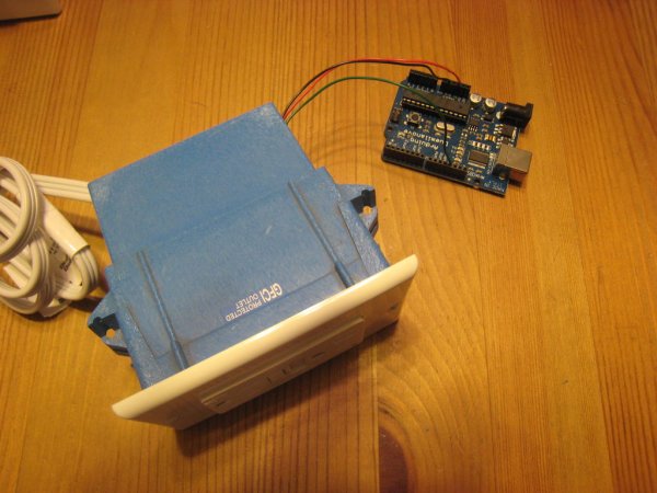
Step 2: Assemble the circuit
Assembling the circuit only takes a few steps. I’ve included pictures of them below and a list of how I built things, which was based upon the height of all the parts.
- Attach the resistors
- Attach the diode
- Attach the transistor
- Attach the three pin screw terminal
- Attach the two pin screw terminal
- Attach the LED
- Attach the Relay
What I learned while doing this is that it’s useful to use the stand to do the smaller parts. When you get to the screw terminals use the table to help you get them on straight. It’s difficult to put on the terminals with the LED on the board because it’s the tallest compent aside from the relay.
Put the relay on last because it gets in the way if you don’t. You will find it to be a little tight against the two pin screw terminal, but that is ok because it still fits. You don’t have to use the two pin screw terminal either and can opt to solder the extension cord directly to the board, but I decided against that for useability.
Step 3: Splicing the Wires
When you splice the extension cord wires you are likely to see one of two things. Either your cord has three different color wires or it doesnt, but there ought to be three or this project won’t work. The three cords are as follows:
- Green – Ground Return
- Black – Hot Wire
- White – Neutral Wire
If your extension cord does not have three wires then you’ll have a green wire in the middle, one smooth wire on one side which carries the voltage (The Black Wire), and one wire with ridges on the other side (The White Wire). Double check these before you make any live electrical connections. Even I messed this up and caught it just in time.
Your going to cut the extension cord about a foot from the end of the female plug. Then split the three wires about 6 inches down. Cut the black wire five inches from the end. This should give you about one inch attached to the cord and a 5 inch extension that will go from your relay board to the outlet.
Next strip and tin the end of all the wires. It’s likely your wires are a collection of smaller wires, twisting them before tinning is a big help. Then lay out everything and check it before moving on.
For more detail: Arduino Controlled Relay Box