This example shows how to send data from a personal computer to an Arduino board to control the brightness of an LED. The data is sent in individual bytes, each of which ranges in value from 0 to 255. Arduino reads these bytes and uses them to set the brightness of the LED.

You can send bytes to the Arduino from any software that can access the computer serial port. Examples for Processingand Max/MSP version 5 are shown below.
Software Required
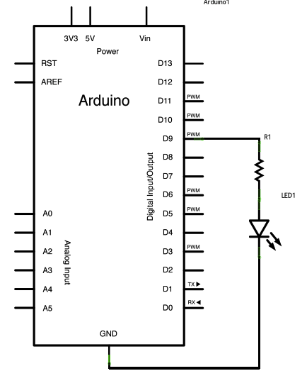
Circuit
An LED connected to pin 9. Use an appropriate resistor as needed. For most common LEDs, you can usually do without the resistor, as the current output of the digital I/O pins is limited.
image developed using Fritzing. For more circuit examples, see the Fritzing project page
Schematic
Code
Dimmer
Demonstrates the sending data from the computer to the Arduino board,
in this case to control the brightness of an LED. The data is sent
in individual bytes, each of which ranges from 0 to 255. Arduino
reads these bytes and uses them to set the brightness of the LED.
The circuit:
LED attached from digital pin 9 to ground.
Serial connection to Processing, Max/MSP, or another serial application
created 2006
by David A. Mellis
modified 30 Aug 2011
by Tom Igoe and Scott Fitzgerald
This example code is in the public domain.
http://www.arduino.cc/en/Tutorial/Dimmer
*/
const int ledPin = 9; // the pin that the LED is attached to
void setup()
{
// initialize the serial communication:
Serial.begin(9600);
// initialize the ledPin as an output:
pinMode(ledPin, OUTPUT);
}
void loop() {
byte brightness;
// check if data has been sent from the computer:
if (Serial.available()) {
// read the most recent byte (which will be from 0 to 255):
brightness = Serial.read();
// set the brightness of the LED:
analogWrite(ledPin, brightness);
}
}
[box color=”#985D00″ bg=”#FFF8CB” font=”verdana” fontsize=”14 ” radius=”20 ” border=”#985D12″ float=”right” head=”Major Components in Project” headbg=”#FFEB70″ headcolor=”#985D00″]
Hardware Required
- Arduino Board
- LED
- 220 ohm resistor
[/box]