Pushbuttons or switches connect two points in a circuit when you press them. This example turns on the built-in LED on pin 13 when you press the button.
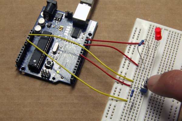
image developed using Fritzing. For more circuit examples, see the Fritzing project page
Connect three wires to the Arduino board. The first two, red and black, connect to the two long vertical rows on the side of the breadboard to provide access to the 5 volt supply and ground. The third wire goes from digital pin 2 to one leg of the pushbutton. That same leg of the button connects through a pull-down resistor (here 10 KOhms) to ground. The other leg of the button connects to the 5 volt supply.
When the pushbutton is open (unpressed) there is no connection between the two legs of the pushbutton, so the pin is connected to ground (through the pull-down resistor) and we read a LOW. When the button is closed (pressed), it makes a connection between its two legs, connecting the pin to 5 volts, so that we read a HIGH.
You can also wire this circuit the opposite way, with a pullup resistor keeping the input HIGH, and going LOW when the button is pressed. If so, the behavior of the sketch will be reversed, with the LED normally on and turning off when you press the button.
If you disconnect the digital i/o pin from everything, the LED may blink erratically. This is because the input is “floating” – that is, it will randomly return either HIGH or LOW. That’s why you need a pull-up or pull-down resistor in the circuit.
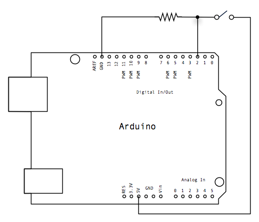
Schematic:
Code
Button
Turns on and off a light emitting diode(LED) connected to digital
pin 13, when pressing a pushbutton attached to pin 2.
The circuit:
* LED attached from pin 13 to ground
* pushbutton attached to pin 2 from +5V
* 10K resistor attached to pin 2 from ground
* Note: on most Arduinos there is already an LED on the board
attached to pin 13.
[box color=”#985D00″ bg=”#FFF8CB” font=”verdana” fontsize=”14 ” radius=”20 ” border=”#985D12″ float=”right” head=”Major Components in Project” headbg=”#FFEB70″ headcolor=”#985D00″]
Hardware
- Arduino Board
- momentary button or switch
- 10K ohm resistor
- breadboard
- hook-up wire
[/box]