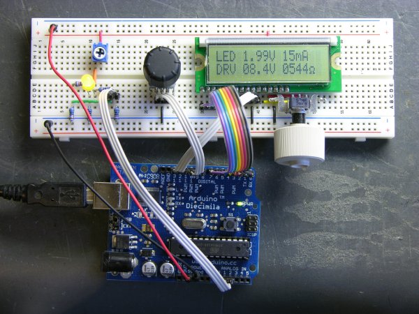
I’m still working on the LED calculator (original idea and most recent work) — I’ve finally got ’round to adding a rotary encoder to set the target system voltage. Now you can turn the potentiometer to set the LED brightness, turn the rotary encoder to set what voltage will be used in the ultimate LED circuit, and read the LED voltage, current, and current-limiting resistor values off the screen.
I also found the Ω in my LCD’s character matrix, so I tidied up the display a little.
And most significantly, I wrote an Arduino library for reading (multiple) quadrature encoders. The simple approach of polling them inside loop() was causing me to lose a lot of steps from the encoders; and the code to read them using hardware external interrupts (lower on the same page) only works on digital pins 2 and 3, so only supports one encoder if both pins are wired to interrupts for the highest resolution, or two if interrupting on a single pin and polling the other.
My Quadrature library uses the TIMER2 overflow interrupt service routine to poll multiple encoders rapidly and track the results, supporting as many encoders as you have room for on the digital pins. It also encapsulates all the dirty work into the library code, so using it is as simple as
#include "Quadrature.h"

Quadrature myencoder1(9, 10);  //  Connected to pins 9 and 10

loop() {
  x = myencoder1.position();
}
It still has some rough edges and it’s by no means perfect (more on that below), but it sure makes it easy to use rotary quadrature encoders. It’s available on a new Downloads page for anyone interested.
How It Works
I’ve discussed previously how rotary quadrature encoders translate the rotation of a shaft into two out-of-phase digital signals from which you can derive both the direction and speed (or steps) of rotation. If you’re not familiar with quadrature encoding and care to follow along, it might be worth a detour to the earlier post to read up on that first.
Before diving into the code, let me say that although I’ve been programming in C for about 25 years, this is my first foray into C++; and everything I’ve figured out about it, I got out of books. I welcome advice on how to write better C++ code.
Decoder
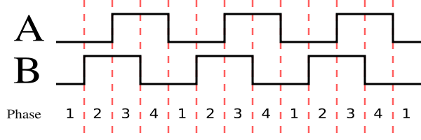
The heart of decoding quadrature is processing transitions. There are various ways of thinking of the transitions, including “on a rising (or falling) edge of pin1, check whether pin2 is high or low to determine the direction” and “on a transition of pin1, XOR pin1 and pin2 to determine the direction.” Some of these don’t even react to every transition in the state diagram (courtesy Wikipedia’s rotary encoder article):
I wanted to be able to detect every transition for the highest possible resolution — but also have the flexibility to switch between “half-stepping” and “full-stepping” to change my resolution, depending on the demands of the application and the encoder. For example, the encoder I’m using in this project has two half steps per physical detent, so I want to be able to set it to read full steps (matching the physical “clicks”) instead of half steps.
It may not be the best way, but I encoded the state change information into a pair of arrays:
const int _half [4][4] = {
    { 0, -1, 1, 0 },            //  00 -> 10 is CW
    { 1, 0, 0, -1 },            //  01 -> 00 is CW
    { -1, 0, 0, 1 },            //  10 -> 11 is CW
    { 0, 1, -1, 0 }             //  11 -> 01 is CW
};

const int _full [4][4] = {
    { 0, 0, 0, 0 },             //  00 -> 10 is silent CW
    { 1, 0, 0, -1 },            //  01 -> 00 is CW
    { -1, 0, 0, 1 },            //  10 -> 11 is CW
    { 0, 0, 0, 0 }              //  11 -> 01 is silent CW
};
Then inside my service routine, I read the current encoder values into the quadbits variable, compare it to the previous value to see whether there’s a change [*], look up the <previous, current> pair in the full-step transition table to see what to add to / subtract from the position accumulator, and then save the current encoder values for the next round through the loop.
            if (quadbits != quad->_previous) {
                int position = quad->_position +
                        _full[quad->_previous][quadbits];
                . . .
                quad->_previous = quadbits;
* [This check isn’t absolutely necessary since no-change is already encoded into the transition tables, but it shortcuts doing min/max checking if no changes have occurred.]
Right now, it’s hard-coded to use the _full[] transition table all the time, since that’s what I needed for this circuit, but it’ll be a simple matter to add another class function to select half- or full-stepping mode and choose the appropriate table here.
For more detail: LED Calculator with Rotary Quadrature Encoder for Target System Voltage Selection using Arduino