I’ve been visiting local convenience store (Dollarama, here in Montreal, Canada) and notice nice looking FM Radio, just for only $3. Why not to try to interface it to my lovely Arduino? Idea looks quite challenging, the same time what is the point in interfacing a DSP radio shield to arduino? I don’t need a radio, I want to have fun experimenting with it, so lets go to the bare metal!
You, probably, could find the same or very similar radio all around the globe, with two buttons user interface, powered by two AAA or one CR2032 coin battery (like in my case), and low price. Hardware design based on IC TDA7088 (depending on the manufacturer, may be “clones” SC1088, SA1088, CD9088, D7088, or YD9088). My radio has YD9088 inside. Quick search on a Google, brings a data sheet. I’d say, It’s not very informative, but at least it shows basic application circuit.
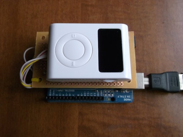
HARDWARE.
The most difficult part of this project, is soldering to surface mount radio components. In minimum configuration just two wires, “interfacing” two front-panel buttons. (Other two, for powering up the radio from arduino +3.3 V on-board voltage regulator instead of battery, should be much easier to attach). I solder wires to the caps, on the side, which connected to the pins 15 and 16 of the IC. In this case, there is minimum impact on usability of the radio, as buttons were not touch. May be important for debugging. If your soldering skills are not as good as mine, you could solder to the traces, removing buttons. On the pictures below you would find two more wires, attached to pin 1 and to earphone’s jack-connector, but they are not in use in this project, and you could left them out.
If you look at the electrical drawings of the shield, you would notice 1 k pot. I build a first version using just two resistors divider, as it shown in “Reset” signal line. But it turns out, that IC is quite capricious for the voltage level it senses on the “Scan” input. On some occasions, it refused to change a station, and in some it flipped to “reset”. Trim the pot, to get voltage at pin 15 about 3.1 – 3.2 V. It would be easy to measure voltage with DMM, temporary changing “delay” in this section of the code:
if (incomingByte == 's') { // SCAN - UPdigitalWrite( scan_pin, HIGH );delay(50);digitalWrite( scan_pin, LOW );}

to 10000 or even 20000. You may need something to be plugged in the earphones jack, as radio is using wires like an antenna. Headphones, or USB speakers cable, works quite well. BTW, the default value 50 may not be enough to “push” a radio up with strong RF signal. Try to send a few “s” simultaneously, “ss” or “ssss”. Setting delay higher than 50 is not recommended, as “jump” may be to wide, so you likely to miss something interesting in broadcasting.
[box color=”#985D00″ bg=”#FFF8CB” font=”verdana” fontsize=”14 ” radius=”20 ” border=”#985D12″ float=”right” head=”Major Components in Project” headbg=”#FFEB70″ headcolor=”#985D00″]Arduino[/box]
For more detail: DIY Arduino FM Radio Shield