I started recently to get interested in building Arduino based robots. Since it is a traumatizing process to take any creation apart, I am opting to keep mine alive and kicking. To lower the cost of this strategy it seems obvious to switch from the arduino development board to selfbuilt arduinos – DIYduinos if you like – and keep the original arduino for what it is meant for… development. See for DIYduino examples the stripduino, the paperduino, the self-etched-arduino, the paperduino perfboard, the palm arduino, and the breadboarduino. There are more out there, I am sure. Just start looking. However, making the cheapest DIYduino requires buying ATMEGAs without bootloader. With those you need to load the bootloader and subsequently you can upload a sketch. This process can be done with a regular Arduino board and is described in a number of tutorials such as the ArduinoToBreadboard tutorial.
Here in this instructable, my first by the way, I am introducing you to a strip board arduino shield that allows you to load either (i) a bootloader or (ii) a sketch onto an ATMEGA using an Arduino board as the In-System Programmer (ISP) or as the USB to Serial interface, respectively. With this board all you need to do is set a few jumpers and temporarily remove the ATMEGAx28 from your original Arduino to switch from one to the other.
Step 1: What you need
The first picture shows all the parts that are needed for building the bootloader/programming shield:
1) Stripboard, 0.1″ hole distance
2) Quick connect IC socket
3) 10kOhm resistor
4 ) 5×2 & 1×3 Pin male/male connector with short/long legs, 0.1″ hole distance
5) 1×8 & 1×10 Pin male/male connector with long/long legs, 0.1″ hole distance (this may differ with the type of original arduino you are using)
6) 2 Cables with female/female connector
7) 2x 22pF Ceramic capacitor
8) 1x 16MHz oscillating quartz
9) 4x Jumper from for example an old motherboard
10) Jumper wires of various lengths
11) 1x ATMEGA328 or 168 to be programmed
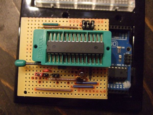
The second picture shows the hardware that I used to put it all together.
1) Solder iron & solder
2) Carpet knife
3) Hand saw with skinny blade
4) File – not too coarse
5) Wire cutters
6) Fine tipped pliers
7) Sharpie Markers of different colors and pencil
8) Third Hand (made by following instructable by rstraugh …thanks)
9) Track Cutter (made by following instructable by scraptopower …much obliged)
10) Voltmeter with test leads
11) Paper printout of strip board pattern
12) Arduino with USB to serial chip (e.g. Arduino Uno) for uploading the bootloader or DIYduino and for subbing in as a USBtoSerial programmer for uploading a sketch
Step 2: Schematic
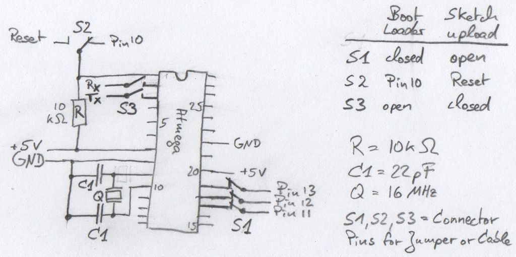
To create the strip board layout I first determined the schematic I wanted to create. You can essentially do a strip board design with any schematic no matter if you invented it, downloaded it, or re-engineered it. In my case I took the connection layout given in the ArduinoToBreadboard tutorial for both uploading the bootloader as well as uploading a sketch and combined them into one schematic adding a few switches. The result is shown in the figure. Note that the switches were realized using typical motherboard jumpers.
Bootloader configuration (as shown in figure):
S1 is closed (i.e. Pins 11, 12, and 13 are connected to the Atmega)
S2 is switched to Pin10
S3 is open (i.e. Rx and Tx are not connected to the ATMEGA).
Sketch upload configuration:
S1 is open(i.e. Pins 11, 12, and 13 are not connected)
S2 is switched to Reset
S3 is connecting Rx and Tx to the ATMEGA328
The schematic further shows the connections of +5V and ground (GND), the 16 MHz oscillating quartz (Q) and its 22pF ceramic capacitors (C1), the 10kOhm pull-up resistor (R), and of course the ATMEGA328.
Step 3: Creating The Strip Board Layout
I took a paper copy of my empty strip board, which I am showing here only as a convenient download opportunity, and started to transfer the schematic onto the paper. I prefer old school paper, but there are programs such as VeeCAD that you can use to create your strip board layout as well.
In the layout figure the ovals represent connectors or “jumper switches”, the lines represent jumper wires, the dotted line represents the IC socket, and the red X and lines represent track interruptions. I also drew the electronic components into the figure, the orange thing is the oscillating quartz.
To create this layout, I started with the connectors that connect the strip board to the Arduino, i.e. the long oval shapes on the lower left and right. These connectors determined the maximum width I wanted to use.
I made a point in verifying if the holes of the strip board would line up with the connectors of my Arduino Uno R3. And guess what? They didn’t. At least not all of them. The connection section that contains Arduino pins 0 – 7, i.e. the Rx and Tx pins, was offset downwards with respect to the shown drawing orientation by 0.05″. This made it impossible to directly connect the strip board (0.1″ hole pattern) to all Arduino connectors using a shield type approach. As an easy and actually convenient workaround I decided to connect to Rx and Tx using cables as you’ll see further below.
After fixing the connector locations, I placed the quick connect IC socket, then the wire jumpers and the other parts first on paper, then, to test things out, in reality. I tried to make good use of the traces that were already on the strip board. That’s the whole point of using a strip board in the first place.
Last I decided where to put the trace interruptions. In the layout figure an interruption is represented by the red X or the red/black line that divides switch S1. These are drawn from the top, but are implemented from the bottom. Watch out to put them in the correct locations
Note that there is one wire jumper placed below the IC socket. This wire jumper was shortened to not penetrate the board. It is only present at the track side of the board.
Also note that the figure of layout is correct, but the photographs may have an error or two, that I tried to highlight with pop-up notes. I had for example an extra track interruption in my actual board. Easy to fix, but avoidable if you check everything carefully.
Step 4: Populating the Stripboard (no main connectors yet)
I double checked everything, although triple checking seems the way to go since I still had a few mistakes that squeezed by. However, I marked the locations of all parts (red dots), the track interruptions (red crosses), and the outline of the board on the top of the strip board. In the figure the black marks are either old markings or errors that I “blacked out” so that I could ignore them for what they were. Not too pretty but the marking did serve it’s purpose. To recreate this layout, use the paper version from step 3 and not the figures shown here, to avoid duplication of the errors that I had to fix.
I took my handsaw and cut out the outline of the shield strip board. With the file I deburred the edges and subsequently inspected all edges to ensure that no traces were shorted.
Next I took my fantastic DIY track cutter and put all the track interruptions into the board. To not get confused, every now and then I stuck a wire through a marked hole from the top to easily keep track of the correct locations.
To create switch S1 with old fashioned jumpers, I determined the location of the switch contacts and with the carpet knife carefully cut away the 3 traces between each of the two connector holes. The 2 part connector was subsequently soldered on the board so that the jumper could bridge the interruption. I confirmed that the track was fully interrupted by testing it with the voltmeter.
When all interruptions were completed, I moved on to put the jumper wires and the resistor on the board and soldered them to the tracks. I chose to populate the board using the parts with the lowest height first. This allowed me to lay the board on its back for soldering. I gradually moved on to higher and higher components using the same strategy until I was done.
Step 5: Soldering the Main Connectors
I chose to use male/male connector pins with long pins on both sides (long/long) for the plug in connections to the Arduino. This created a little bit more offset to the Arduino’s USB cable jack and reduced the danger of shorts.
I inserted and soldered the connectors from the bottom of the board. First, I fastened regular scotch tape on top of the board at both connector locations as shown in the figure for one connector. Then I placed the actual connectors in the Arduino and rested my shield on top held up only by the tape.
From below I tacked on the connectors at two pins with some solder. This allowed me to remove the shield from the Arduino and properly solder all connector contacts.
[box color=”#985D00″ bg=”#FFF8CB” font=”verdana” fontsize=”14 ” radius=”20 ” border=”#985D12″ float=”right” head=”Major Components in Project” headbg=”#FFEB70″ headcolor=”#985D00″]
Duemilanove
straightforward
interruptions
old fashioned
[/box]
For more detail: ArduinoISP Bootloader/Programmer Combination Shield