MIT has developed a fantastic visual programming language called Scratch. It is also an amazing learning tool for children, because it is simple, cute, and by providing interaction with the real world by a board called “Scratch Sensor Board”.
This Instructable shows the development of a shield for Arduino that can interact with Scratch and replicates the functions of the “Scratch Sensor Board”
Note: The present shield constitutes a so called ‘derivative’ from “Scratch Sensor Board”, whose license can be found here. Further information about the original board can be found here
For the Impatient:
Final Arduino Sketch is here
Printed Circuito Board is here (eagle)
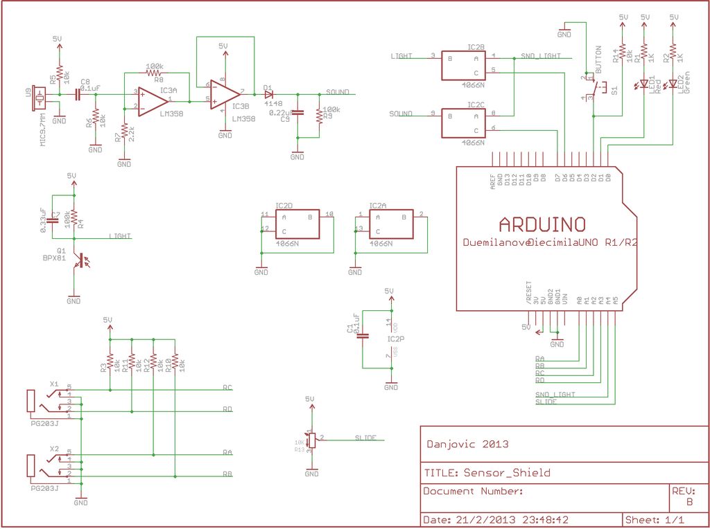
Schematics are here (pdf / eagle)
Step 1: Preparing Ground
The first thing to do is read the documentation (here) to find how do the Sensor Board interacts with Scratch.
After some time reading we found that the Sensor Board communication occurs via RS-232 at a speed of 38400 baud. It is good, because Arduino already have a Serial Port which means less circuits to implement.
The protocol between Scratch and Sensor Board constitutes of a ping pong mechanism. First Scratch application send a a data byte to the board then the board replies with sensor data. Nice.
The request packet is simply a byte with the value 0x01, whilst the sensor data consists of 9 high byte / low byte pairs (i.e. 18 bytes) spaced in time by a 400us interval.
The high byte / low byte pairs contains a 4 bit channel ID and a 10 bit Value. This is good, because if suits well with Arduino ADCs resolution.
For the Scratch Board Release 1 firmware and Scratch release 1.1 and later, the mapping between channel ID and sensor type is given below:
Channel / Sensor
0 / Resistance D
1 / Resistance C
2 / Resistance B
3 / button
4 / Resistance A
5 / Light
6 / Sound
7 / Slider
8-14 / Not Used
15 / Firmware ID (0x04)
From the 16 possible channels we have 7 analog, 1 discrete (on/off), 1 dummy (firmware-id) and 7 spare (not used now; maybe in a future version).
Step 2: The challenges
Extra Channel
If you know Arduino well and paid attention to the last step, you might be noticed that Scratch expects to receive 7 analog readings, but a Stardard Arduino has only 6 channels. That’s the first challenge.
To accomplish that, the solution found was to implement a multiplex using a 4066 that is a quad bidirectional CMOS analog switch. One at a time each switch is activated and the correspondent ADC channel is read.
The channels choose to be multiplexed were from the ‘light’ and ‘sound’ sensors, since they have stabilizing (filter) capacitors, which make changes in such channels to occur much slower than the switching.
Of course, the switching scheme had to be tested before going on, but luckily, it worked very well!!
DIYable Board
A second challenge was to make this shield DIYable. It implies on a Single-Face board with as few jumpers as possible.
To achieve the single face layout I have started by choosing the place of the connectors and the light and sound sensors. Then the association of the Arduino Pins with sensors, as well as the halves of the OPAMP halves and gates of the Analog Switches were experimented until the ‘ratsnet’ lines showed up aa bit clean. At the end the result was achieved with only 2 jumpers.
(Note: The board available on the files has been further optimized and now only one jumper exists)
Step 3: Board Construction
The prototype board had been built using the ‘tone transfer method’. There are several instructables teaching how to do that.
The board was etched using Ferric Chloride in a water bath to accelerate the reaction. Despite the potential of the Ferric Chloride to make a mess, I prefer to use it because the etching chemical reaction does not release gases. After corrosion the board was silver coated using TP-065E solution and then it was drilled.
Then the components have been soldered starting by the resistors, then the capacitors, followed by the IC Sockets, After that the taller components have been soldered.
Note: Due to a lack in local stock, the prototype received a different potentiometer.
Using a multimeter all the connections have been tested. I always do that before powering things up because It saves us from a lot of trouble. For example I have found a short circuit caused by a track that was too close from the pads of two resistors, but it wasn’t noticed on PCB drawing tool.
(Note: The board available on the files already have this correction)
Step 4: Testing the Board
After the board assembled and checked it’s time to test the individual functions before starting the develop the final sketch.
This practice is called ‘validation’ and its objective is to reduce the amount of uncertainties and/or errors thus avoid having several problems at the same time to solve.
The first tests have been performed on the Resistance Channels using the ‘AnalogInOutSerial’ example form Arduino IDE, where the line below was changed according the desired channel.
[box color=”#985D00″ bg=”#FFF8CB” font=”verdana” fontsize=”14 ” radius=”20 ” border=”#985D12″ float=”right” head=”Major Components in Project” headbg=”#FFEB70″ headcolor=”#985D00″]
Scratch Board
Resistance
Light
Sound
Slider[/box]
For more detail: Scratching with Arduino