Story
The Nokia 5110 is a basic graphic LCD screen for lots of applications. It was originally intended to be used as a cell phone screen. This one is mounted on an easy to solder PCB.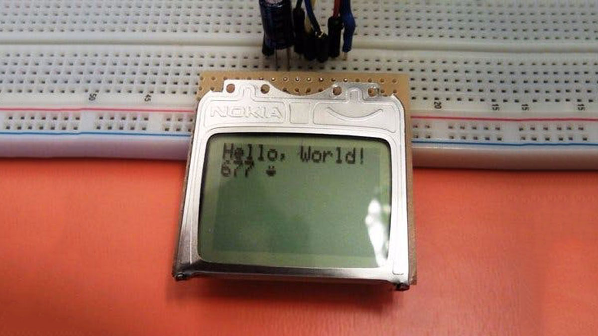
It uses the PCD8544 controller, which is the same used in the Nokia 3310 LCD. The PCD8544 is a low power CMOS LCD controller/driver, designed to drive a graphic display of 48 rows and 84 columns. All necessary functions for the display are provided in a single chip, including on-chip generation of LCD supply and bias voltages, resulting in a minimum of external components and low power consumption. The PCD8544 interfaces to microcontrollers through a serial bus interface.
Display Overview
The Pinout
To interface with and power the graphic LCD, there are two, parallel 8-pin headers above and below it.
Pinout Table :
Pin Number | Pin Label | Pin Function | Input/Output
1 | VCC | Positive power supply | Input
2 | GND | Ground | Input
3 | SCE | Chip select | Input
4 | RST | Reset | Input
5 | D/C | Mode select | Input
6 | DN(MOSI) | Serial data in | Input
7 | SCLK | Serial clock | Input
8 | LED | LED backlight supply | Input
Power Supplies
There are two different supply voltages on the LCD. The most important supply voltage – VCC – supplies the logic circuits inside the LCD. The datasheet states this should be between 2.7 and 3.3V. In a normal state, the LCD will consume about 6 or 7mA.
The second voltage supply is required for the LED backlights on the board. If you were to remove the LCD from the PCB (not that you should, or need to), you’d see that these are backlights in their simplest form – four white LEDs spaced around the edges of the board. You may also notice that there aren’t any current limiting resistors.
This means you have to be careful with this voltage supply. Either stick a current limiting resistor in series with the ‘LED’ pin, or limit the supply to 3.3 V max. The LEDs can pull a lot of current! With nothing to limit them, they’ll pull about 100mA at 3.3 V.
The Control Interface
Built into this LCD is a Philips PCD8544 display controller, which converts the massive parallel interface of the raw LCD to a more convenient serial one. The PCD8544 is controlled through a synchronous serial interface similar to SPI. There are clock (SCLK) and data (DN) input lines, and an active-low chip select (SCE) input as well.
On top of those three serial lines, there is another input – D/C – which tells the display whether the data it’s receiving is a command or displayable data.
For a list of commands, check out the “Instructions” section of the PCD8544 datasheet (page 11). There are instructions to enable clearing of the display, inverting the pixels, powering it down, and more.
Hardware Assembly & Hookup
Assembly
To “assemble” the LCD, you’ll need to solder something to one (or both) of the 8-pin headers. There are plenty of options available here. To make the LCD breadboard-compatible, straight or right-angle male headers can be soldered in.
Otherwise, wires or other connectors can be soldered to the display pins.
Hookup
For the data transmission pins – SCLK and DN(MOSI) – we’ll use the Arduino’s hardware SPI pins, which will help to achieve a faster data transfer. The chip select (SCE), reset (RST), and a data/command (D/C) pins can be connected to any digital I/O pin. Finally, the LED pin should be connected to a PWM-capable Arduino pin, so we can dim the backlight as we please.
Unfortunately, the LCD has a maximum input voltage of 3.6V, so we can’t hook up a standard 5V Arduino straight to it. We need to shift levels. This leads us to a few options for hookup:
- Direct Connect
The easiest hookup is to connect the Arduino pins directly to the LCD.
This setup can work for 5V Arduino’s, ignoring the 3.6V limit on the VCC and data lines. It works. But it may decrease your LCD’s life.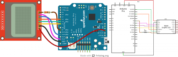
- Limiting Resistors
Sticking resistors in-line with the data signals is a cheap, and easy way to add some protection to the 3.3V lines. If you have an Arduino Uno (or similar 5V ‘duino) and some 10kΩ and 1kΩ resistors lying around, try this:
For more detail: Using Nokia 3310 84×48 LCD with Arduino