Story
A Continuation of One Button Restart of a Stalled Raspberry Pi
In a recent article, I showed how an Arduino Pro Micro can be utilized to send characters to the serial console of the Raspberry Pi Zero W. The Pro Micro was chosen because it is small, inexpensive, and easily acquired plus the integrated USB port provides a convenient way to easily upgrade the programming. (Always disconnect the ProMicro Vcc from the RPi before inserting the USB micro cable into the Pro Micro.)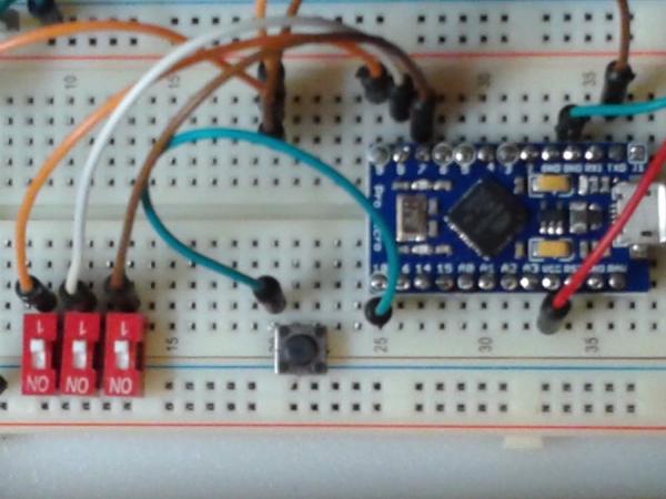
This article will maintain all of the assumptions from the previously referenced article and will concentrate on the Arduino programming side by showing how easily multiple digital pins can be used in tandem to create a numeric value, and then that numeric value can be used to call various functions to perform our requirements using just a single pushbutton to initiate communications with the RPi over the serial console.
What the Program (Sketch) Needs to Accomplish
I already know what I think I want to achieve with the software, but no matter how good you are at pounding out Arduino code, I always advise writing down the overall requirements. Always do this and you will thank yourself down-the-road when you have long forgotten the particulars.
- Should provide multiple command capability, maybe 8 total
- Must be intuitive and easy to use to allow delegation of tasks
- Must be easily updated as Raspbian OS for the RPi does change often
- Sketch should be clear and self-documenting to share with others
- One common button must execute any of the 8 selected sketches
Pins
The original proof-of-concept simply used a single button to print to the serial Tx port of the Arduino which was connected to the Rx0 input of the RPi Zero W. That was fine for a POC. Now that I want at least 8 separate and perhaps complex command sets, I need a way to select each individually. Three of the Arduino digital pins will provide 2^3 combinations which is perfect. Because of their physical positions, I elected to utilize D7, D8, and D9. Therefore, I moved the pushbutton to D10 just for convenience.
2^3 (2 raised to the 3rd power) is eight combinations and is generally described as 0 – 7 (zero through seven.) This computer stuff is far easier to visualize in a table:
Logic Table x == no connection(default) 0 == Grounded
2^0 2^1 2^2
Decimal /-------Pins------/ Function call
Value D7 D8 D9
0 0 0 0 zero()
1 x 0 0 one()
2 0 x 0 two()
3 x x 0 three()
4 0 0 x four()
5 x 0 x five()
6 0 x x six()
7 x x x seven()
Arduino Pins
In understanding the above, I need to provide a little insight into the Arduino digital pins. Pins can be input or output; in output mode, the value of a pin can be logic 0 (low) or can be logic 1 (high.) But we will be using input mode, so the value being “feed” to the pin must be high or low. Arduino logical statements actually understand the concept of high and low and if I enable the digital pins as an input, I can also enable a pull-up resistor value (weak pullup) so that an open (unconnected) input pin will always read a digital high value. Therefore, if all 3 of D7, D8, D9 are open then they are truly high because the weak pullup inside the IC is ensuring the high value. To change the combined octal value of the three inputs, I only need to ground (Gnd) one or more pins to create a logic low level. A very simple (and unsophisticated) function was written to create the resulting 0 – 7 number.
int nValue (void) {
 uint8_t temp = 0;
 if( digitalRead( 9 )) temp += 4;
 if( digitalRead( 8 )) temp += 2;
 if( digitalRead( 7 )) temp += 1;
return temp;
}
Well that was easy! Therefore, with D9, D8, and D7 all open (default), the function will return 7. As jumpers (or DIP switches) are used to select the On/off conditions (On == connected to Gnd) then the value returned will range from 7 to 0. Perfect. Pay careful attention here… If a switch is ON, then the corresponding digital pin is going to be pulled to logic low because we are connecting the switch commons to Ground (Gnd.)
So far, no magic required: just some simple straight forward application of basic logic. That is a good thing. The whole process could be made very ugly by striving for low-level access to the digital port. While such changes would be far more efficient, the complexity is simply not necessary in a machine that cycles only once every 1000 mS. Keep it simple – keep your sanity.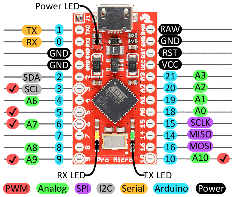
Functions
By now, I have completed the bulk of the program, at least in my head. I know from experience that I must have code in setup() to initialize serial communications and I know from experience that all the work will be done in loop(). I made a decision in creating the truth-table above which may not be obvious yet: I decided that each 8 states would be provided through separate functions. That is, if the value from the 3 buttons is 0, I must write a function that I already defined as having the name zero(). If the octal value is 7, then I have already pre-named the function in the chart to be seven(). You can call it Fred() or Sam() or Sue(), but I am too simple minded to go on that trip with you (this time!)
For more detail: RPi Serial Console Automation Using Arduino