More VideoBlasting
So why didn’t the TV out library reach any higher resolution than 160×100?
The answer is simple.
They did not use any hardware on chip to push the pixels out.
If you use the SPI to push the pixel you will gain an immediate 1:1 in pixel speed
The SPI push out data at the CPU clock / 2.
That is the maximum speed that the chip is capable of.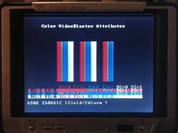
On a 16MHz chip, that is an impressive 8mbps.
That is really fast, 8000000/sec data bits!
On a TV you have around 64uS time to draw a single line (around taking NTSC/PAL in account)
That means you have hardware to push out 512pixels in that interval.
The no good SPI
So why not use SPI for the pixel pushing?
There is one flaw in the ATmega SPI hardware.
It shifts out 8pixels and delays for one pixel before working on our next 8pixels.
Why?
It is an SPI interface and has to conform to that protocol and that states that there should be a high 9bit after a transfer.
Not good for us. Not at all
We need 8bits, one byte, back to back drawing our videoline.
There is a solution to this.
The USART.
Yes I know its the serial communication via USB to your computer.
But it it has a huge advantage.
It can run at the same speed as the SPI interface but no 9th bit.
That’s right. Unlike the SPI port it doesn’t do the extra bit.
This is exactly what we need.
The VideoBlaster resistor mixer
The resistor mixer adds the sync and pixeldata to a composite videosignal.
If looking at the NTSC video signal, the 1K resistor is adding 0.3v level sync pulses and the 470ohm resistor is the 0.7v pixel or video data.
When summing it becomes the 1vp-p CBVS signal (Composite Blanking and Video Sync) or composite video.
It is the same circuit that all TVout sketches use but we connect the video resistor to the TX pin instead of a digitalpin.
It works on all ATmegas and Arduinoboards even if its connected to a computer.
You loose the serial debugging but not the serial uploading.
But you gain a videooutput and that can display your serial text instead of sending it to the computer.
And the pixelshifter runs at Fcpu/2 and that meens 512pixels/line at Fcpu 16MHz.
To be able to generate the NTSC Chromasignal Fcpu needs to be 14.318MHz
If not exactly that it will still show the image but it will be in B/W.
AVR VideoBlaster
I’ve been on the net for a while and so have all of you.
Ever since I started with the Arduino and after that, the ATmega chip, I was always fascinated of doing video on the chip.
The chip is fully capable of doing video with its 16MIPS processing power. But B/W video isn’t very funny. At least not to me.
TVout is one of the things that many people come across.
That gives you B/W composite video graphics on a TV screen.
In a 160×100 maximum resolution.
That is actually a very good resolution for a TV display.
But still in Black&White
What I did was to take the TVout 2 steps further.
I made the resolution 320×200 and in color.
Yes, I broke the imaginary border.
You read it right the first time.
That is 40×25 characters in text and a dazzling 320×200 in graphics.
And its all in color.
(Yes that is 40×25 textmode on any Uno/Nano but only in B/W)
High resolution color on a single ATmega chip.
I’ll show you the real circuit and the code.
The 1284 schematics
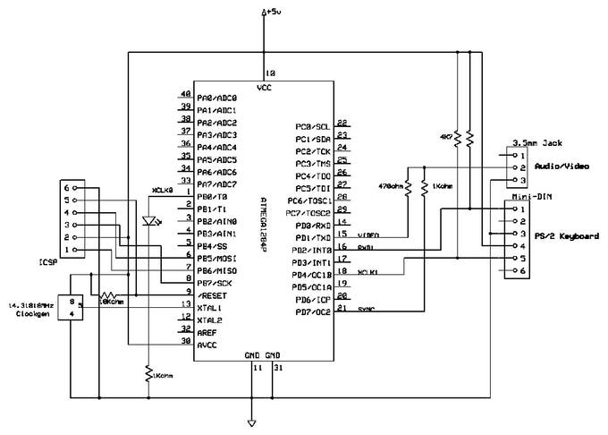
For more detail: AVR VideoBlaster