Hello everyone, em here today with an interesting tutorial on using position wheels using your favorite Arduino. The whole idea behind this article is to explain the logic behind position wheels, the way it works and how to implement it in your project. If you prefer to see the explanation in the form of a video rather than an article, please visit my Video tutorial in Youtube.
WORKING PRINCIPLE OF POSITION WHEELS:
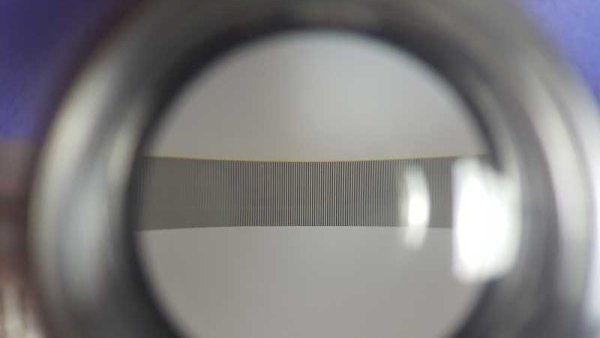
The position wheels / band is a transparent piece of thin plastic which is divided into small segments made out of non transparent lines with transparent lines in between them. They come in various sizes and you can find them with divisions ranging in the few ten’s or even less and up to a few thousands, depending on the amount of accuracy that is required by the mechanism it is attached to.
USING IR SENSOR TO TRACK MOVEMENT:
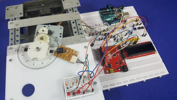
Next we have a type of dual IR sensor attached to the mechanism. This sensor is a simple IR LED combined with an IR receiver and each time that the wheel moves or the sensor itself moves across a band, the output signal from the IR receiver will change depending on the amount of IR light that is passed through the transparent/non transparent segments. In short, assuming that we have a sensor with two outputs that we call A and B, if A has a non transparent line between its LED and the receiver and B has transparent line between the LED and its receiver, the output of the sensor will be LOW on A and HIGH on B. If it was the other way around then the output of the sensor would be HIGH on A and LOW on B. Also there can also be states where both sensors have the same setting and then both will provide the same output of either being HIGH or LOW, but these states are insignificant for this tutorial.
USING POSITION STRIPS TO CALIBRATE MOVEMENT:
First of all we need to understand how we can count those changes in the states of A and B. Then using that to figure out how many steps the wheel has moved in either direction. Also we need to use some extra code and a calibration mechanism to detect the exact position of the wheel with relation to the clock or any other predefined fixed comparison values.
In the video example I have used a wheel which I have salvaged out of an old inkjet printer and it has 1800 steps which if divided by 360 degrees provide a One degree movement for every 5 steps. In order to count the steps the code in the Arduino which is attached to the sensor will only regard a single condition where either the output of A is HIGH and the output of B is LOW, OR, the output of A is LOW and the output of B is HIGH.
CALIBRATING CONDITIONS:
Let’s take a look at first conditional state, what will happen when the wheel is turned is that one time there will be a transparent line between the LED and receiver of output A which will provide a HIGH output. And at the same time there will be a non transparent line on the LED and receiver of output B which will provide a LOW output . This exact state is achieved by the precise spacing between the two sensors inside the packaging as it is fabricated by the manufacturer. This will be considered by the code as a single step.
On the next movement this condition will change and eventually be reversed where A will become LOW as now it has a non transparent line on it and B will become HIGH as it has a transparent line on it. This condition will be disregarded by the code and will not be counted. Eventually as can be seen in the video demonstration we will get exactly 1800 steps for each full rotation.
INCREASING PRECISION:
What will happen if we decide to take into account both of the conditions is simple. We will be doubling the amount of steps which we will be counting and we can now call them half steps. As mentioned earlier, 1800 divided by 360 provides a fixed movement of One degree for each five steps. Divide One degree by 5 and you get 0.2 degrees for each full step (where we count only a single conditional state of the A and B sensor outputs), divide the 5 full steps by Two to get half steps and we get a movement of 0.1 degree for each half step, essentially allowing us to count 3600 movement for each full rotation of the wheel and obviously allowing us to achieve a greater measure of accuracy.
USES OF POSITION WHEELS :
Looking at the above from an application point of view if we were to utilize a position wheel on a rotating camera mount for example (even if only manually moved without the aid of a motor), we could effectively point the camera in 3600 different positions for each full rotation of the mount. And if for example we wanted to plot the movement of an object in a circular motion around a fixed point, we could plot 3600 different points for each full rotation.
Read More: How to use position wheels with your Arduino