A light meter is a device that measures the intensity of light. It finds applications in schools, hospitals, production areas, passageways and more to measure and maintain proper lighting levels. It is often used by photographers to determine the proper exposure for a photograph. Today we are going to build a simple light meter using an Arduino board and a BH1750 digital light sensor. The measured lighting level or intensity is displayed on eight seven segment LED displays, in both Lux and Foot-candle units.
Hardware
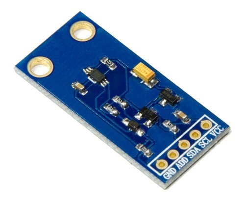
Shawon Shahryiar posted a project article before about making a lux meter using a simple LDR. His project used an inexpensive photo sensor to detect the light intensity. In order to convert the measured light intensity into Lux, he needed to calibrate the photo sensor first using an external reference photometer. This project is an improvement over that as it uses the BH1750FVI sensor to measure the ambient lighting level. BH1750FVI is a calibrated digital light sensor IC that measures the incident light intensity and converts it into a 16-bit digital number. It can measure ambient light intensity ranging from 0 to 65535 Lux (L). The Lux is an SI unit for illuminance and is equal to one lumen per square meter. The BH1750FVI sensor directly gives output in Lux. The spectral response function of the sensor is approximately close to that of the human eye. The sensor output can be accessed through an I2C interface. The 7-bit I2C address is 0x23 if the ADDR pin is grounded, or 0x5C if ADDR is tied to VCC. In this project, I am using the BH1750FVI sensor module from Elecrow.
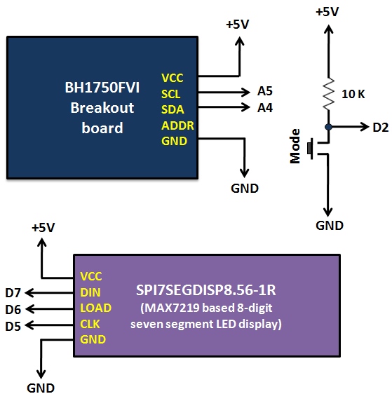
For the display part, I am using the SPI7SEGDISP8.56-1R module, which is an 8-digit serial seven segment LED display based on the MAX7219 IC. It requires only 3 I/O pins and provides full control of all the LED segments. The Arduino board used in this project is called Crowduino, which is 100% compatible with Arduino Duemilanove. A tact switch connected to Digital Pin 2 (interrupt 0) of Crowduino is used as ‘Mode’ select to toggle between Lux (L) and Foot-candle (Fc) units of display. The following picture shows the connections of the BH1750FVI sensor board, the SPI7SEGDISP8.56-1R display, and the tact switch to the Arduino board.
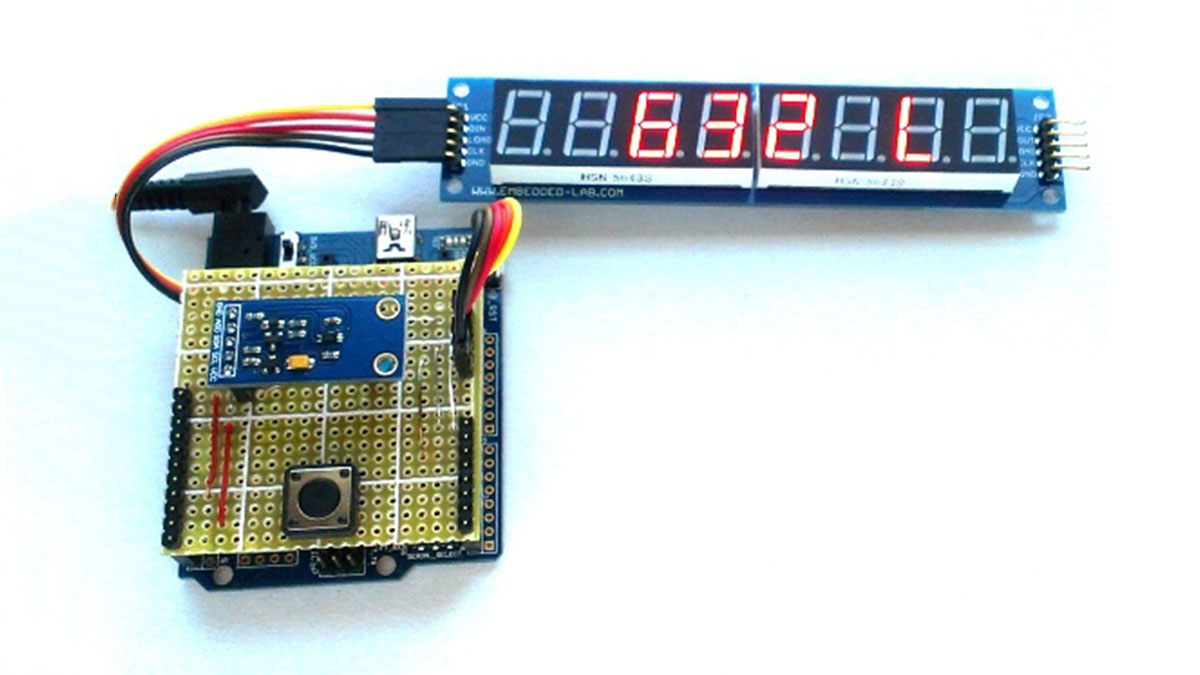
I have soldered the tact switch and the BH1750FVI sensor module on a general purpose prototyping board, which plugs onto the Crowduino board using male headers. An easier way to setup the hardware for this project would be to use an Arduino prototyping shield. Since I didn’t have a spare proto shield, I made one by myself. The following picture shows the complete hardware setup for this project.
Read More: A simple digital light meter using Arduino and BH1750FVI sensor