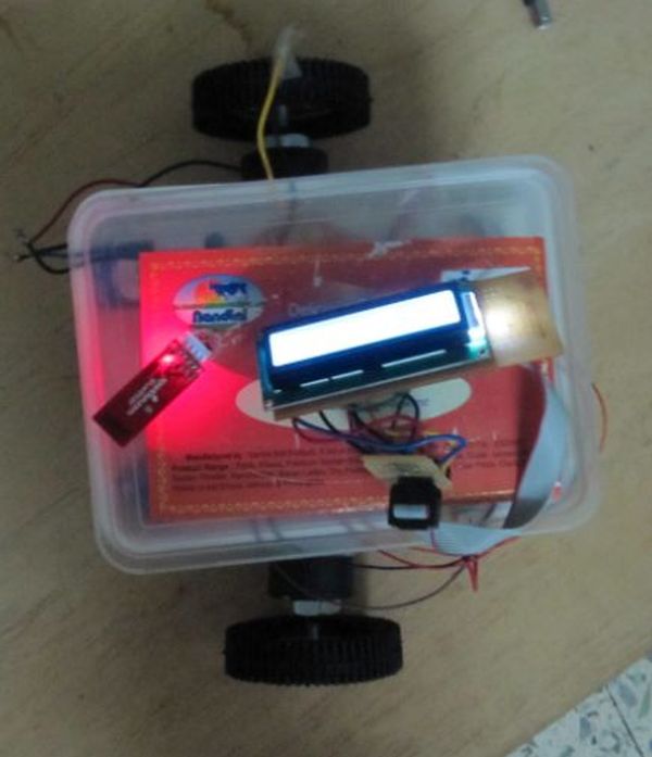
This is an instructable for a bluetooth controlled Message Droid. I call it R2Blue2. It moves around and displays messages that you type using your phone or computer. Atleast it was supposed to. Due to many problems such as underpowered batteries and bad cable management I wasn’t able to extract the performance necessary. I will explain the problems that plagued this build later.
The messages are sent over a bluetooth connection between the sender and the bot. For my usage, I used a HTC WIldfire running the Blueterm application to send serial commands to bot. The bluetooth module I used on the bot is Bluesmirf Gold which has a default baud rate as 115200. I don’t have an FTDI cable to change the baud rate. The baud rate setting shouldn’t matter much but whatever is the baud rate of the module, you should set up a serial port of the same baud rate in the arduino code. Otherwise you’ll get undefined states and the bot won’t function as wanted < imagine R2D2 scream >.
Step 1: Parts
Arduino Deumilanove
Bluesmirf Gold (or any suitable bluetooth module)
Double line LCD based on the Hitachi HD44780 (most common)
Two 100 rpm geared motors
L298 motor driver
10K potentiometer
Birch strip
Connectors for the birch strip
Ribbon Cable
Lots of single strand wire
General Purpose Board (GPB) ……. if you choose to solder everything
Breadboard
Zip ties
Solder (lots of it if you choose to solder everything)
If you can procure a Arduino shield kit, things will be much easier and more reliable as the present connections to the arduino are not very tight. In India, a shield board is quite expensive and I couldn’t find it any where I searched. (if you are from Bangalore and are an electronics geek, you should be familiar with SP Road :P). total cost is about 80 to 100 dollars. The bluesmirf is the most expensive part at 60 dollars.
Step 2: LCD wiring
The LCD was wired up as shown in the tutorial on LadyAda. I just soldered everything on to a pcb and made an
extension for it using the ribbon cable to allow it to be flexible. I also used a birch strip to make it easily
detachable.
link for the tutorial: www.ladyada.net/learn/lcd/charlcd.html
The connections are tabulated below for easy reference:
Pins Connections
1 Ground
2 +5V
3 Contrast Adjustment Pot
4 Arduino pin 2
5 Ground (always in write mode)
6 Arduino pin 3
7 No connection
8 No connection
9 No connection
10 No connection
11 Arduino pin 4
12 Arduino pin 5
13 Arduino pin 6
14 Arduino pin 7
15 +5V
16 Ground
Step 3: Motor driver wiring
The L298 doesn’t come in a standard DIP (dual inline package). Hence you can’t mount it on a breadboard. You
have to solder it onto a GPB. This is what I did and drew some wires out of every pin to allow for connection to
the arduino and the bread board.
The pin connections are tabulated below for easy reference:
Pins Connection
1 Ground
2 Pin 1 of motor 1
3 Pin 2 of motor 1
4 9V supply of motor
5 Arduino pin 8
6 +5V from arduino
7 Arduino pin 9
8 Ground
9 +5V from arduino
10 Arduino pin 10
11 +5V from arduino
12 Arduino pin 11
13 Pin 1 of motor 2
14 Pin 2 of motor 2
15 Ground
This is the easiest connection scheme and it uses the least no of arduino pins, 4. I have made the enables always

high by connecting them to +5V and the current sensing always low by connecting to ground. Look at the pin
[box color=”#985D00″ bg=”#FFF8CB” font=”verdana” fontsize=”14 ” radius=”20 ” border=”#985D12″ float=”right” head=”Major Components in Project” headbg=”#FFEB70″ headcolor=”#985D00″]Arduino Deumilanove
Bluesmirf Gold (or any suitable bluetooth module)
Double line LCD based on the Hitachi HD44780 (most common)
Two 100 rpm geared motors
L298 motor driver
10K potentiometer
Birch strip
Connectors for the birch strip
Ribbon Cable
Lots of single strand wire
General Purpose Board (GPB) ……. if you choose to solder everything
Breadboard
Zip ties
Solder (lots of it if you choose to solder everything)
If you can procure a Arduino shield kit, things will be much easier and more reliable as the present connections to the arduino are not very tight. In India, a shield board is quite expensive and I couldn’t find it any where I searched. (if you are from Bangalore and are an electronics geek, you should be familiar with SP Road :P). total cost is about 80 to 100 dollars. The bluesmirf is the most expensive part at 60 dollars.[/box]
For more detail: Bluetooth Controlled Message Droid using Arduino