There are probably thousands of articles on making an Arduino. So who needs another Arduino? Well, this Lazy Old Geek(L.O.G.) needs one. Here’s the features I would like:
Features:
Low cost
More permanent than a breadboard
Not a custom PCB
More prototyping area than a RBBB or Anarduino or Boarduino
Easier prototyping than just perfboards
Compatible with USB-BUB and my Arduino USB
Step 1: Parts List:
Most of the electronic parts were purchased or can be purchased and are priced from:
http://www.taydaelectronics.com/servlet/StoreFront
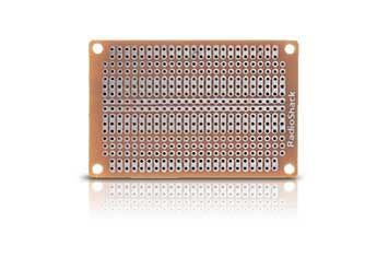
Radio Shack Multipurpose PC Board with 417 Holes $2.19
http://www.radioshack.com/product/index.jsp?productId=2102845
1 AtMega328 IC bootloader $4.00 (ebay?)
1 28 pin IC socket $0.07
1 16MHz resonator $0.17
1 10K resistor $0.01
2 0.1uFd capacitors $0.02
1 6pin male header $0.02
Optional LED:
1 1k resistor $0.01
1 LED $0.01
Optional 3V Aref:
(Don’t install these unless your script requires Aref to be set to 3 volts.)
1 3.2K resistor $0.01
My Arduino USB $3.99
My calculations says that’s about $10.50 for a working Arduino clone with USB. I think that’s a pretty good price.
Step 2: R.S. Multipurpose PCB
Radio Shack Multipurpose PC Board with 417 Holes $2.19
Why I chose this board:
Designed for standard ICs, similar to breadboards
Two strips running between ‘IC pins’ for power and ground
Connected outside rows
The component side is painted to match the copper side
Now using this PCB is similar to using a breadboard but one of the difficulties at least for this Lazy Old Geek is that you put the components on the non-copper side but make most of your connections on the solder side.
Another difficulty is using the two center strips as power and ground.
Well, I came up with a clever way of designing and documenting the PCB layout. I do not have much expertise with CAD software like Eagle so I used Microsoft Excel. If you are not familiar, Excel is a spreadsheet program that can create documents that can also be read by Open Office and Google Docs.
What I did is create a spreadsheet where each hole in the PCB is represented by a cell in the spreadsheet (See picture or ArduinoTemplate.xls). So this is a representation of the physical PCB. When adjacent pads are connected like the strips down the middle I filled the cells with the same color.
The cells contain descriptions of what’s in them for this circuit.
E.g., the AtMega socket is labeled for pins 1-28.
NOTE: The picture/spreadsheet represents the solder side or bottom of the IC, so the pins are opposite what you might expect. For the AtMega off to the sides, I put in some signal descriptions.
I also labeled the ground (light blue) and power strips (pink)
Components are marked by the holes where they will be put.
E.g., C1 and C1. The resonator has three pins so it is Rs, Rs, Rs.
The six pin male header for the USB adapter is called RS232 and is identified by its pin names, Gnd, 3.3V, 5V, Tx, Rx, DTR
Resistors and capacitors have two lead and they are located by the same identifier, e.g. C1 for one lead and C1 for the other. Further instructions are at the bottom.
 ArduinoTemplate.xls18 KB
Step 3: Soldering it up
Soldering to these copper pads is not easy. After sitting around, the copper oxidizes. It would probably help if you scrubbed it with Scotch Brite or maybe an eraser.
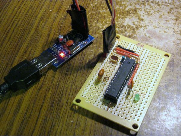
One of the difficult parts is wiring up power (5v) and ground for the AtMega IC. Now sometimes if the signal and pin are the same side, it’s just a matter of soldering a little jumper across.
22 Gnd
7 5V
But sometimes they cross over
20 5V
8 Gnd
For these, I took a stiff piece of wire and jumpered over the other bus. (see picture). The wire is stiff and short so shouldn’t bend very easily. Now this is probably not the best way to do this but it works for me. If this concerns you, you can put some insulation on the wire.
[box color=”#985D00″ bg=”#FFF8CB” font=”verdana” fontsize=”14 ” radius=”20 ” border=”#985D12″ float=”right” head=”Major Components in Project” headbg=”#FFEB70″ headcolor=”#985D00″]
Low cost
More permanent than a breadboard
Not a custom PCB[/box]
For more detail: L.O.G. $10 Arduino