So you just bought this Arduino kit or Arduino-clone kit. You spent hours inserting parts and soldering components. You connect everything up and turn it on and stare at the little LED. You wait a second and nothing happens. You wait a minute and still nothing happens.
So what do you do?
Well, I have the answer for you! You pack it up and send it to the Lazy Old Geek. No charge, no questions asked, no suspicious stares!
Plan B is you can try to fix it. This is plan B.
The first tool you’ll need is a good set of eyes. Now, my eyes aren’t so good. I used a magnifying lamp.
1. Look through the documentation. Arduino clones come in all sorts and sizes. Now I’m assuming that yours has an ATmega chip. And most kits use the Blink sketch to test the board. So read through the documentation and make sure that you have everything connected right. That means any jumpers, USB or other power source and any switches set. Correct anything you need to.
Also, make sure the ATmega in the kit is preprogrammed with a blink sketch. If not, the instructions should tell you how to load it.
2. Still no blinky. Use those eyes to look over the Printed Circuit Board (PCB).
Look for missing components (sometimes a kit may not require all the components marked on a PCB, check documentation)
Look for components installed backwards:
Diodes are the little black or glass cylinders with a single band on one end. Diodes allow current (electricity) to flow in only one direction so if they’re installed backwards, current won’t flow. The band should be shown on the PCB.
Electrolytic capacitors are the bigger black cylinders. They are designed for current to go only one way through them. If installed backwards, they could blow up. All these capacitors have a grey stripe on one side. This is the negative side and should be shown on the PCB. The smaller caps aren’t polarized and can be put in either way.
LEDs are Light Emitting Diodes. Since they are diodes, they allow current to go only in one direction.
TIP: All of the assembly instructions tell you that the longer lead on an LED is positive and then they tell you to install and cut off the leads! If you look closely at the LED at the base where the leads come out, you will see a flat spot on one side of the circle. See picture. This is the negative side. The PCB is usually marked with a + on one side often with a flattened circle on the other.
ICs are Integrated Circuits, those little black chips with lots of pins coming out. Most Arduino kits use the ATmega168 or ATmega328. Make sure the notch at one end matches the notch on the PCB (and the socket). While you are at it, make sure none of the ATmega pins are bent underneath the IC rather than going into the socket. See picture.
TIP: Most new ICs have their pins flayed out and won’t go into a socket very easily. I like to roll the IC (see picture) on both sides so the pins line up easier.
You’re not done looking yet. Flip the PCB over and look for the following:
Cold or missing solder joints (see pictures). The second one might work but should be resoldered. All solder joints should be shiny and silver not grainy and grey.
TIP: If you have trouble fixing a cold solder joint, sometimes the component lead is contaminated. Try to remove the component or at least the component lead and clean it with isopropyl alcohol. Now you should be able to solder it.
Make sure all of the pins on the 28 pin socket are sticking out. (You might have a pin on the socket bent under.
Solder bridges (see picture). Remove them.
Non-essential Info: I actually found a solder bridge on my Freeduino. It was on some pins that I hadn’t used yet.
Fix any problems and try again.
Step 1: More Troubleshooting
So it’s still not working. We’re going to dig a little deeper.
Tools: DMM (Digital MultiMeter). There are ways to troubleshoot without one but I don’t know them. I’ve included a separate step on how to use a DMM.
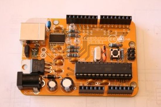
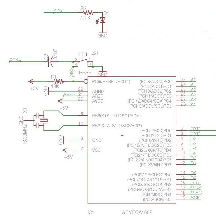
The first picture is a schematic. This is taken from an Anarduino (Arduino) clone and shows everything that is needed to make it blink. The same requirements apply for any Arduino. The second picture is the Anarduino itself. Everything in the schematic is on the Anarduino. (I did remove some of the components from the schematic to simplify it)
Schematic: is an electrical representation of an electronic system usually using symbols. The symbols represent the components on the PCB. The lines connecting the symbols (components) are the metal traces (wires) on the PCB.
INFO: The ATmega chip microcontroller is the ‘brain’ of the Arduino. See picture.
Blink requirements are:
+5V on pin 7 of the ATmega
Ground on pin 8 of the ATmega
+5V on pin 1 of the ATmega (Reset pin. If it is low, the microcontroller won’t work)
16MHz oscillation on pins 9,10 of the ATmega
Blink sketch in the ATmega
The resistor/LED connected to pin 19 of the ATmega.
INFO: 16MHz crystal oscillator/ceramic resonator generates the ‘heartbeat’ of the ATmega. Basically, it tells the ATmega to go from one step to the next in an Arduino sketch. Without it, the ATmega would just sit there.
TIP: Some of you may have noticed that the Blink sketch refers to Digital pin 13 but the LED is connected to ATmega pin 19. Well, the Arduino team decided to number their Analog and Digital connections in sequence and call them pins. For old timers like me, I think of pins as IC pins so I wish they would have called them something else.
INFO: In the schematic, the ATmega pin 19 is labeled SCK. If you go to the top of the schematic, you will also see an SCK label connected to a resistor and an LED. When 5V is on pin 19, the LED should light.
INFO: Whenever you see a line on a schematic with a label, that means it is connected somewhere else with the same label. Some labels, like GND may have several connections. Labels make schematics easier to read. Just imagine even this simple schematic with all the labels connected.
Troubleshooting:
3.1 The first step is to connect the Arduino up to power and make sure it is getting to the ATmega.
Set your DMM to DC Volts with range of greater than 5V.
Carefully measure the voltage from pin 8 to pin 7 on the chip. It should be around 5 volts. If not, then go to the next Instructable step. In my particular setup using USB, my 5V is only 4.85V. This is okay.
3.2 Check the voltage on pin 1 of the chip. It should also be around 5 volts. If it’s 0 volts, check all of the components around pin 1. The most likely problems would be the reset switch installed 90 degrees off or a defective switch.
3.3 It’s harder to tell if the oscillator circuit is working. If your DMM has a frequency (Hz) setting you might be able to measure the frequency (16MHz). My DMM has a frequency setting but apparently doesn’t go that high.
I am fairly certain the following will work. Measure the DC voltage from pin 8 or any ground to pin 9, then 10. Both of them should be greater than 0 but less than 5V. I have an Arduino with a crystal that measured 0.14V and 1.25V and one with a resonator that measured 0.79V and 0.58V. If one or both sides are at 0V or 5V then it’s probably not oscillating. If all the connections are okay, then it’s probably a bad crystal or resonator as those little capacitors rarely fail.
3.4 Here’s a little trick to see if the Blink program is running. Connect your DMM to ground and ATmega pin 19. The voltage should go from 0V to 5V and back every second. If this isn’t working, then your ATmega probably isn’t programmed or is damaged. Reprogram it or if you have another one, try it.
3.5 If this is working, check the top of the resistor (in this case R2). It should also be changing for 0 to 5V. If it stays at 0V then you have an open connection between pin 19 and the resistor.
3.6 Check the voltage on the other side of the resistor. If it is changing from 0V to 5V, then either the LED is backwards or it is open. If it is 0V then your LED is probably shorted. In a working circuit, it should be changing for 0V to about 1.5V.
You should have found your problem by now and fixed it or ordered parts.
[box color=”#985D00″ bg=”#FFF8CB” font=”verdana” fontsize=”14 ” radius=”20 ” border=”#985D12″ float=”right” head=”Major Components in Project” headbg=”#FFEB70″ headcolor=”#985D00″]Arduino[/box]
For more detail: Arudino- No Blinky