There is a saying: “If all you have is a hammer, everything looks like a nail”. Well, when I see a display, I think of clocks 🙂
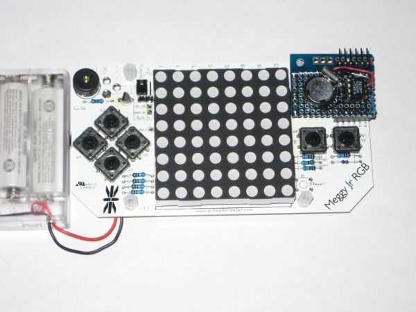
I will show you here how to easily make a simple digital clock by hacking Meggy Jr RGB. This is an Arduino-programmable device, featuring an 8×8 RGB LED matrix, a few buttons and a buzzer. Ideal candidate for an alarm clock.
The clock will use the ubiquitous DS1307 as RTC (real-time-clock). This chip can be bought on ebay or digikey/mouser for about $1.
You will ask why we need an RTC chip at all. Why can’t we just count the seconds and calculate the minute, hour, day, week, month and year with the on-board ATmega328? Of course we can. We would only need to write and test a bunch of functions. But who is going to record the passing of time when the processor is not powered? DS1307 does all these for us: for only $1 or so, it counts the seconds for as along as the coin battery lasts (which is a few years) and increments the minutes, hours, days etc., and even keeps track of leap years. All we need to do to get the current time is to ask the little frugal RTC chip for it.
Here are the requirements (or the few issues to think about):
1. build a small RTC breakout board (“BOB”), according to the datasheet (basically connecting the crystal and coin backup battery to the DS1307 chip);
2. make the RTC BOB fit somewhere nicely over the Meggy Jr board;
3. connect this RTC BOB to the Meggy Jr board, as cleanly as possible, with no wires soldered to the Meggy Jr board.
This tutorial will show how I solved these minor challenges.
Step 1: The Parts
Beside a working Meggy Jr RGB, here is the complete list of things we will need for this project:
- DS1307 and a 8-pin socket;
- crystal (32768Hz);
- coin battery (CR1220) and a holder for it;
- a small piece of prototyping board;
- 2 pieces of 6-pin female header;
- 6-pin right-angle male header;
- a few wires.
Of course, we will also use a soldering iron, solder and desoldering wick (flux pen is also recommended).
Step 2: Understanding the challenges
As I said previously, there are few issues to think about, and especially:
- size and placement of the RTC BOB;
- connecting the RTC BOB to the Meggy Jr board only through the plug-in headers.
A bit of background.
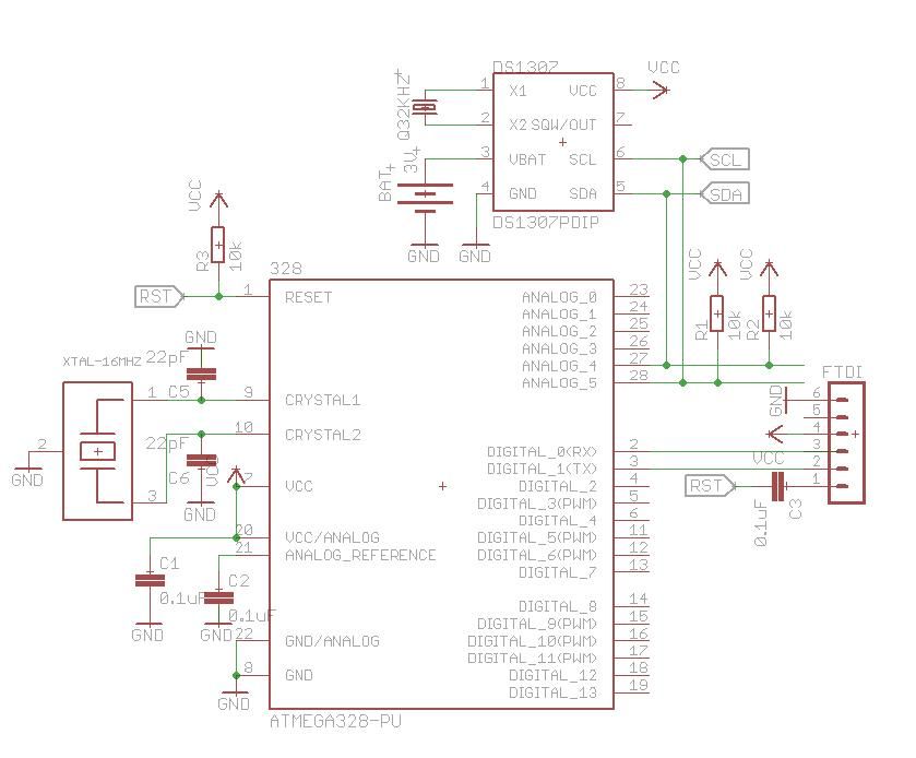
DS1307 talks with a host processor on I2C interface, also known as “two wires”. This interface uses two lines, named SDA and SCL.
DS1307 has a set of these (pins 5 and 6, respectively), as has ATmega328 (pins 27 and 28, respectively). We will need to connect these pins as shown in the attached schematic.
Meggy Jr board makes SDA and SCL available through the headers PC4 and PC5, highlighted in the image below.
To power the DS1307 chip we will also need the 5V line (Vcc) and the ground (GND). Since we don’t want to solder wires to the Meggy Jr board, we will take them somehow from the FTDI connector, shown highlighted in the last image.
Step 3: Preparing the Meggy Jr board
To avoid soldering wires between the RTC BOB and Meggy Jr board, we will use headers, Arduino-style.
One of the headers will be placed in the freely available connections named “PC0” through “PC5”. This header will provide access to SDA and SCL signals.
The second header will replace the FTDI connector and it will provide the necessary power (5V) and ground. We still need an FTDI connector to program the device, so we will re-create it on the RTC BOB.
So go ahead and carefully remove the FTDI connector. The desoldering wick comes handy in this case. Make sure you moist it with the flux pen before every use. After most of the solder is gone, the 6-pin header can be pulled out pin-by-pin, with some pliers. After the 6 holes are clean (use a safety pin to go through each hole, since the solder does not stick to it), place and solder the 6-pin female header.
After soldering both headers, the Meggy Jr board will look as shown in the photos below.
One more step is required here: connecting the 5V line to the “FTDI header”, by soldering a short wire (a cut-off resistor terminal can be used) as shown in the diagram, with the red line.
[box color=”#985D00″ bg=”#FFF8CB” font=”verdana” fontsize=”14 ” radius=”20 ” border=”#985D12″ float=”right” head=”Major Components in Project” headbg=”#FFEB70″ headcolor=”#985D00″]Arduino
- DS1307 and a 8-pin socket;
- crystal (32768Hz);
- coin battery (CR1220) and a holder for it;
[/box]
For more detail: Clock with Meggy Jr RGB using Arduino