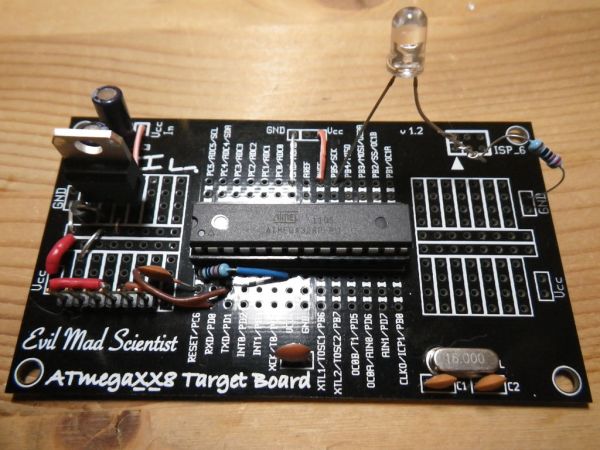
I have been making my own Arduino’s on strip-board but recently bought some of the Evil Mad Scientist ATmegaxx8 Target Boards.
While they weren’t designed as an Arduino board they are perfect to use as they have:
– places for the crystal and capacitors (XTL and C1, C2) or resonator
– place for the power smoothing capacitor (C3 on the board)
– place for the 100nF capacitor across VCC and Gnd, pins 7 & 8 (C4)
– have 4 prototype spaces on the board which can hold 2x 14pin DIP chips
– has 3 holes per Arduino pin to solder leads to
– has bus lines suitable for 5V and ground
In this Instructable I am using 2 of the 4 prototype areas, one for the 5V regulator and one for the FTDI headers. If you are going to use a 5V supply like a wall wart then you won’t need the regulator and if you want to program the AVR chip in a regular Arduino and move it into this board then you won’t require the FTDI headers.
For a schematic I base my build on the minimalist Arduino circuit found at thetransistor.com
Step 1: What you need
28 Pin IC socket (or 2x 14 pin)
ATmega328P with Arduino firmware
16 MHz Crystal
2x 22pF capacitors
2x .1uF capacitors
2x 10uF electrolytic capacitors
LM7805 5V regulator
IN4001 diode
6-pin header
100k 1/4w resistor
hookup wire
LED and 220ohm resistor for testing
For a schematic I base my build on the minimalist Arduino circuit found at thetransistor.com
Step 2: Socket
Solder in the IC socket – I used 2x 14 pin sockets for this build.
Notch to the left.
Step 3: Crystal & caps
Solder in the crystal and 22pF caps
Alternatively you could use a 16MHz resonator instead of the crystal and without the capacitors.
Step 4: 5V regulator
I am using the top left prototype space for the 5V regulator and caps as it is next to where the C3 is.
There are 7 “buses” and I use the first 4.
Starting on the left will be Vin (from wall wart or batteries), then LM7805 Vin, then GND, then LM7805 Vout (5V)
Between the Vin and LM7805 Vin I put a protection diode (IN4001 or similar)
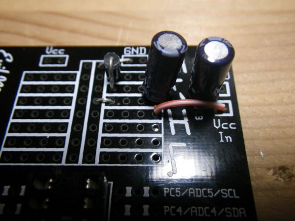
There are 2x 10uF electrolytic caps used for power smoothing – one goes across the LM7805 Vin and GND, the other goes across LM7805 Vout and ground. One goes on the prototype area, the other in C3.
Start by jumpering from the GND space to the long bus and over to the 3rd row from the left (1st picture)
Next solder in the diode as shown, stripe to the top (2nd picture)
Next solder in the 2 10uF caps minus to ground (3rd & 4th pictures)
Next jumper between the 4th row and Vcc In, this will take the 5V regulated power and supply it to the board (5th picture)
Next solder in the LM7805 (6th & 7th picture)
[box color=”#985D00″ bg=”#FFF8CB” font=”verdana” fontsize=”14 ” radius=”20 ” border=”#985D12″ float=”right” head=”Major Components in Project” headbg=”#FFEB70″ headcolor=”#985D00″]ATmegaXX8 Target Board
28 Pin IC socket (or 2x 14 pin)
ATmega328P with Arduino firmware
16 MHz Crystal[/box]
For more detail: Arduino from Evil Mad Scientist ATmegaxx8 Target Board


