I have been working on this project for a while and whilst it is still under development I decided to write a short guide after several requests to do so. The dimmer uses an interrupt driven XL-Maxsonar EZ1 ultrasound range finder to measure the distance between the sensor and your hand. By moving your hand up and down over the sensor you can increase or decrease the amount of light emitted by the connected halogen lamp.
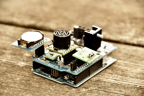
In this post I will explain how one can make the basic dimmer based on a simplified circuit. This dimmer later evolved to include an LCD, SHT15 temperature and humidity sensor, DS1307 realtime clock and a mosfet driver to drive the mosfet above 30Khz so the unpleasant dimmer humming noise would disappear. I will talk more about this later.
First things first, here’s a movie of the latest version of the dimmer in action, it includes an LCD, a temperature and humidity sensor, a realtime clock and an alarm function that simulates a sunrise:
Dimmer Circuit
To build this dimmer one should first connect the Ultrasound Sensor to the Arduino and make sure one can get reliable data from it:
Further one should use a capacitor to smooth out the power supply to the sensor. I found that this results in babytv.com much less noise in the readings from the sensor and is thus a must.
The Dimmer circuit uses an optocoupler to decouple the power supply of the halogen lamp from the Arduino. Whilst this is not necessary it is certainly good practice and might save your Arduino in case something goes wrong
Once the sensor and the halogen lamp is wired up as shown in the above diagrams the basic version of the dimmer is finished. You should now be able to use the code at the bottom of the page to get your dimmer working.
Humming Dimmer
One of the biggest issues for me at the beginning of this project was the high-pitched humming noise that the dimmer circuit would make. Whilst inaudible during the day, I found the noise very unpleasant when reading in the evening. The worst part of it was that when I programmed an alarm function to be awoken by a simulated sunrise it was actually the high pitched noise that got me out of bed rather than a gentle virtual sunrise….
So I went ahead and recorded the sound my circuit was making with an Edirol recorder. A spectrum analysis of the recording nicely shows that in certain frequency bands we had a constant noise. Below is the recording at the standard Arduino PWM rate of 488Hz.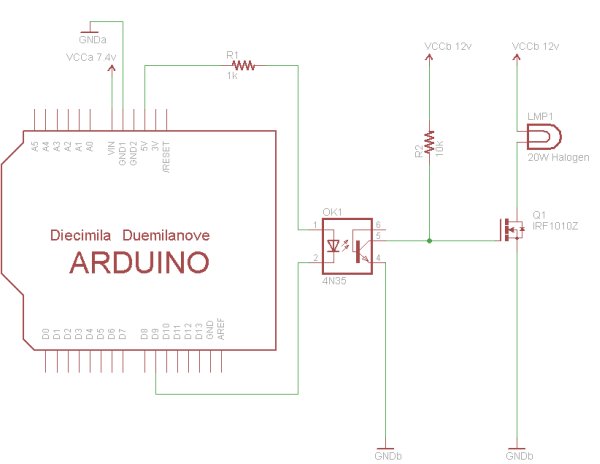
Whilst this may look like random noise changing the pwm frequency to 3900Hz yielded a much clearer picture.
It became evident that the frequencies of the humming noise where exact multiples of the pwm frequency. Based on these results the goal was to increase the PWM frequency of the Arduino above the human hearing range which is roughly 15-
20000Hz. However the circuit I initially used would not allow for the mosfet gate to be charged and discharged fast enough at a frequency above 5000Hz so I needed a mosfet driver to do the job. And as expected, with the mosfet driver I was able to switch the mosfet at 31Khz and the humming was no longer audible.
For more detail: Ultrasonic Dimmer (Without Humming Or Buzzing Noise)