This instructable describes how a simple but powerful webserver used for controlling of home appliances can be done. The hart of the circuit is the ATmega328 microcontroller. I have chose this because I wanted to use all available Arduino libraries compatible with them. The Ethernet chip used is ENC28J60. A lot of Arduino libraries exist also for it. The webserver is designed in the way that it control 4 channels (3 LED’s and a relay). It have two outputs for “status”/”mode” LED’s (which of course can be used also for control of other devices). I have used one analog input for some sensor (can be LDR, thermoresistor, thermometer chip, hall sensor, current monitor chip like ACS712…etc).The webserver has two buttons – first for reset, and the second for mode selection or some additional settings. A power indicator LED shows if the webserver is supplied or not.
The movie above demonstrates the webserver functioning using a simple basic program.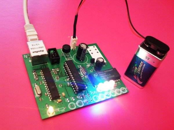
Step 1: Design description
The schematic of the webserver is shown on the picture. There can be seen the three channels, each controlling a pair of LED’s. Here LED’s are meant in more wide aspect – they can be standard LED’s, but also could be LED’s, which are parts of optocouplers used for relay control as these on the picture above. It could be also combination of LED indicating if the relay is activated and the optocoupler. On the schematic diagram can be seen also both “status”/”mode” LED indicators. Using binary encoding they could show for example which mode of four available is active in the moment or to give some other useful information. Looking at the schematic can be noticed also that the power supply circuitry consist of three different power chips, which seems to work together in parallel. This is not true :-). This approach of schematics drawing gives further, when designing the PCB, to place there three different footprints of these chips and finally to solder only one, but having a big choice for alternatives. The current PCB supports linear regulators in SOT223 and TO263 packages, as well the National Semiconductors (TI) “simple switcher” regulator LM2825N (both versions: adjustable or fixed voltage 3.3V). Using switching power supply in this case may be is better solution because of the higher power efficiency comparing with the linear one. The ENC28J60 chips is consuming relatively high current and the power loss in the linear regulator can be high. I have soldered LM2825N-3.3. (The supply must be kept in these limits, because the ENC28J60 can be burned at 5V!)
The design files in “Eagle” format are available for download. They can be used and modified freely without asking of permission. From there can be extracted the part list. I will not give here the whole BOM. I will describe only the most specific parts.
As I said : the microcontroller used is the ATmega328 in DIP28 package.Can be used also the low power version ATmega328P. Here you should be careful with the chip signatures used by the Arduino programmer – for both chips they differ. How to solve the problem can be seen here. The ETH chip is ENC28J60 in DIP package. On the PCB there is place where a Zettler relay AZ733-2C-12DE can be soldered, but it is optional. The most exotic part in the whole design is the Ethernet jack with embedded magnets “HanRun” HR911105A. The passive devices are mainly SMD. This could be problem for people not having experience with soldering of these devices, but in this site can be found a lot of instructions about this.
Step 2: Pictures of the fabricated PCB
On the picture can be seen the dual layer fabricated PCB
Step 3: Almost ready device …
The pictures show a populated PCB. Not all possible devices are soldered, but this is not always necessary. Depending on the use, some devices can be soldered or not, or simply replaced with others. For example: instead R25 a lot of other devices can connected – various temperature, light, humidity, voltage, current….and so..and so sensors can be attached. Instead the LED’s at the PCB periphery optocouplers, triacs , MOS transistor switches or solid state relay can be connected.
Here I want to mention two things:
1) It is highly recommended that the ATmega328 chip is put on socket and can be extracted for programming
2) Although, there is SPI connector on the PCB, which could be used for the programming on place of the ATmega chip, it can create problems….
– a programmer working with 3.3V must be used, because the microcontroller and the Ethernet chip share the same power supply. If this voltage is overridden the ENC28J60 can be burned out.
– both chips share the same SPI bus, and a conflict could appear.
Other solution could be to put the ENC28J60 chip on socket and to solder the ATmega328 chip. In this case, before each programming the ETH chip should be removed and after that inserted back. The connection to the power supply chip of the webserver should be cut also by the use of the jumper JP4.
I personally programmed the ATmega328 chip on a breadboard using cheap USBtinyISP programmer from ebay. (see the next step).
Step 4: Programming setup
Programming of the microcontroller was done using the setup shown above.
I did not burn a bootloader in the chip. For programming I have used the “Load the sketch using programmer” menu item of the Arduino IDE.
A simple code switching ON/OFF 3 LED channels and the relay is attached to this step. Some explanation about the code will be given later.
For more detail: Webserver for home appliances control