News: In this latest months I’ve made some important fixes and improvements to the code and to the webserver of the project. See datura_mega_v19.ino for the latest code.
The most functional project over internet – Use it as a complete irrigation system for your garden, or use it to control your aquarium, or just to control any kind of devices at home. The imagination is the only limit.
Features
- Arduino programmed
- Assign a name to each of 6 relays (you can connect lamps, pumps, elettrovalves, heaters, ecc.)
- Choose between manual and automatic mode for each relay
- Full week routing time programming (each relay has his own settings of course)
- Sensor control (you can attach up to 6 analog sensor and set parameters to control the on/off state, as a light sensor, or a moisture sensor, ecc ecc)
- Fully web controlled
- Password protected
- Temperature, pressure and humidity display and log
- DisplayDigital clock with battery backup
- Log statistic data on SD (temp, humidity, analog sensor of each relay and switch on/off states)
Yes, I know it is not a project for novices, as you need some basic soldering skills to build the project, and you’ll have to etch your own Datura (layout drawings available to download) shields to attach to Arduino, and you’ll have to have a bit of arduino knowledge.
BUT, you can do it! And when done, you’ll be the happiest person in this world, as I was when I built it for the first time. It implies a bit of problem solving, as you could find different components, or you could need some adjustment, but bite one problem at time, and you will see that you can really do it.
Simplifying, If you attach all the components directly to the arduino (take a look at the photo), you will wonder that you won’t need the shields.. so, why you need 3 shields to build? Because you can eradicate a jungle of wiring mess.
The project target is simple. Imagine that you need to action 2 water pumps, and a couple of fans for air flow, and 2 lamps. You can use a pump (or an elettrovalve) to send clear water to your plants, and another pump to send fertilized water.
Every relay can be time programmed. As an example you can set 12 hours of light to your plants, and irrigate 2 times, as in the morning and in the evening. You can also connect a couple of wires to the pot, and the other two ends to the sensor ports. Simply set moisture humidity, so, if the terrain is already wet, the resistance between the 2 cables in the pot will decrease, and Datura will not switch on the relay.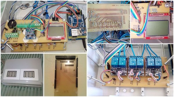
Or imagine your aquarium/terrarium which you have to control. You can connect a filter pump, an UV filter and set timer to sterilize water, lamps, you can connect an heater carpet, or a heater wire and control the water temperature. You can connect a Ph sensor, and regulate nitrates. You can constantly control humidity and temperature in your terrarium. You can also simply connect lamps to the power outlets, and manually switch on/off from internet.
Datura uses also an optional cheap nokia display to show all the informations about humidity and temperature. It show also all the information about each relay. You can set rotation info speed by parameter.
Datura lets to enable a log which write every 30 minutes temperature and relays state in a csv file (in the sd root), so you have all the history recorded. The Ethernet shield lets to control Datura from a simple and comfortable web page. You can also assign a password to protect control from unauthorized people.
The web control is fully functional, and simple to manage. Costs The total cost is about 100€ or 130$. Keep in mind that the most expensive components are the Arduino Mega (20€), the ethernet shield (12€), the box (15€), and the power outlets (20€).
Step 1: Materials
- Arduino Mega 2560 + libraries attached
- Ethernet shield w5100
- DHT22 temperature/humidity sensor
- DS1307 real time clock
- 3 x 20x10cm 1 side copper pcb (see drawings for size specifications)
- 6 x relays 5v 10A-250V
- lcd nokia lhp7366 (nokia 5110 o 3110) – warning! it need 3v. 10k resistances needed on all pins to limit current.
- 5 x 10k 1/4watt resistances
- 12x 8 pin pcb connectors with long feet and at least 80 pin headers + 2×3 iscp header (see pics) with long feet
- 6 x pcb connectors terminal block
- 1x 8 pin socket Dupont Wire50 Female dupont Jumper Cables (20cm approx)
- 12 pcbplastic pinspacers
- a little piece of sanding paper (400) and alchool to clean pcb
- 30x20x10cm plastic box6 wall power outlets
- Electric wires for relays
- A 7-9v power supply for arduino
- ferric chloride to etch your pcbs
- press n peel transfer paper, or glossy laser printer paper and laser printer CD pen or Staedtler lumocolor to refine pcb tracks.
- Drill and and tiny drill bits: 0.75, 1mm and 2,5mm.
All the items needed are easily available on ebay.
Step 2: Build up the shield
yes, you’ll build 3 shields.
All the pin mapping is included and explained in the arduino code attached.
Datura shield is simply an adaptor shield, placed between arduino and Ethernet shield, which simplify the wiring components arrangement. Relay shield is a board which let you to arrange relay in a comfortable displacement. The board really simplifies your build. Sensors shield allow to connect the ds1307 clock 8pin DIP, the clock backup battery, and the connectors for all the external sensors you could use to better control your relays. It also permit to connect the display (in the pdf I also painted alternatives display board connectors, so you can also wire it with a long flat cable to comfortably place in a panel).
N.B. Note that I’ve added an external ds1307 clock board on the shield as an ebay seller sent me by mistake instead of nude DIP package. No problem, simply connect the 4 wires to the pin headers on the prearranged shield.
Print and etch Datura shield, sensors shield and relay shield
You can easily find detailed tutorials to etch correctly pcb boards, but I’ll fast describe for simplicity.
Sand the pcb and clear the copper surface with alchol to remove scratches and grease on the copper.
Print the pcb layouts and check the right print size (try first on normal paper and see if it fits on arduino board). Print on glossy photo paper and use iron to transfer on the pcb surface. Tipically glossy paper needs 6-7 minutes with iron at max temperature, to transfer all the toner to the pcb. Use a piece of fabric between iron and paper. Keep pressed and don’t move the iron at least for 2-3 minutes, then you can gently move the iron in circles over all the pcb to let the toner transfer better.
Let the pcb cools down a bit, then immerge the pcb in water for some minute, then start to remove paper. If everything went fine, the toner should remains on the copper. Use the cd pen to fix the tracks if you find some broken. Use gloves and a pair of glasses, and fill a plastic box with some acid, then immerge the pcb into. Let the acid coversPrint and etch Datura shield, sensors shield and relay shield completely the boards. If you move constantly the box, the acid will remove the exposed copper in a few minutes (15-30 minutes). Ok, when done, wash the pcb and clean the boards from the acid with water. Follow the drawings and drill the holes for the components.
Place and solder the components on the boards
Start from Datura shield and solder all the pin pcb connector with the long feet and the icsp connector, then solder the pcb headers.
Solder the jumpers and the pin headers on the Relay shield. I placed the relay pins connector on both left and right side on shield, so you can choose to connect the flat on the side you want. Now connect the relay boards with the plastic spacers. You will find that this arrangement is quite easy to manage. At last take the Sensors shield and solder the 8 pin socket. Then follow the battery holder (keep an eye to + and -). Now solder all the green connectors, that will let you to connect eventual external analog sensors.
On the board I also added 2 more connectors, named A and B, on the bottom of the board. The B connector is used to attach the DHT22 humidity/temperature sensor, and the A connector is for future use (flow control).
Complete the board by solding all the remaining pin header needed as you see in the photos.
N.B. If you have a different display check the pinout before connect to the shield. Pinout is shown in the header of arduino code. Of course, before power on the arduino, double check all the shields and connections for mistakes and test with a multimeter for shorts. First of all, if you find shorts between + and ground, well.. something went wrong.. so resolve the problem before powering the arduino. Double check is better than burn a component and waiting for another shipment.
When you are sure that everything is ok, you can power on the arduino. and upload a simple example sketch as blinking led. If everything is ok, then you can go to the next step.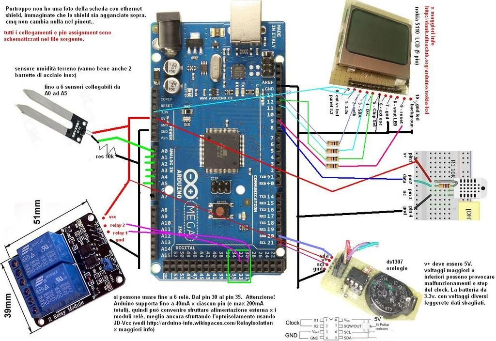
Step 3: Arduino code and wiring
Well, in attachment you will find the code and libraries needed to compile the code.
Simply unzip the libraries and copy to your arduino folder
- datura_mega_v18.ino is the code
- dht22.zip – the humidity temperature sensor library
- adafriut_pcd8544.zip – display chars library
- adafruit_gfx.zip – display graphic library
- ethernet.zip – ethernet library
- realtimeclock ds1307.zip – clock library
- sd.zip – microsd library
EEPROM memory mapping
// eeprom(0) = n_rel – number of relays connected
// eeprom(1) = log on/off
// eeprom(10-15) = auto/manual relay mode
// eeprom(20-27) = pwd
// eeprom(30-41) = max humidity (2 byte x valore)
// eeprom(100-147) = relay names
// eeprom(1001-1168) = Timer 1 table on/off
// eeprom(1169-1336) = Timer 2 table on/off
// pinout:
// A0,A1,A2,A3,A4,A5 parameter sensors (analog values 0-1023)
// 4 arduino – CS SD card
// 6 arduino – reserved (lcd activation)
// 44 arduino – DHT22 temp/hum sensor
// 46 arduino – Flow sensor
// 10 ethernet reserved (needed for arduino uno compatibility)
// ==> pin 1 lcd – v+ 3.3 arduino
// 13 arduino ==> pin 2 lcd – Serial clock out (SCLK) (10k res needed)
// 11 arduino ==> pin 3 lcd – Serial data out (DIN) (10k res needed)
// 12 arduino ==> pin 4 lcd – Data/Command select (D/C)(10k res needed)
// pin Gnd arduino ==> pin 5 lcd – LCD chip select (CS)
// ==> pin 6 lcd – LCD oscillatore est – not connected
// pin Gnd arduino ==> pin 7 lcd – GND
// ==> pin 8 lcd – Vout – optional led backlight
// 9 arduino ==> pin 9 lcd – Reset (10k res needed)
// 20 arduino ==> pin SDA RTC DS1307
// 21 arduino ==> pin SCLK RTC DS1307
// 30,31,32,33,34,35 relays
// 53 arduino – ethernet reserved
Once uploaded the code on arduino, it’s time to fire it on. BUT DON’T CONNECT high voltage to relay! you’ll connect later, at the last.
You shuld see also the display working and cicling between relays.
For more detail: Datura 6 home automation – 2015 improvements