Age Group: 13 – 18
My experimental rover that I built from a Roll-A-Way alarm clock that was on clearance for $5.
It can be controlled via the numeric section of a keyboard when the serial port is connected to a computer or
a Wii Nunchuck attached directly to it, using either the joystick portion, or the accelerometer while pressing the bigger button.
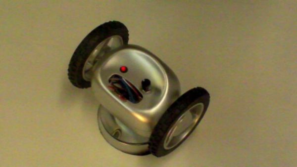
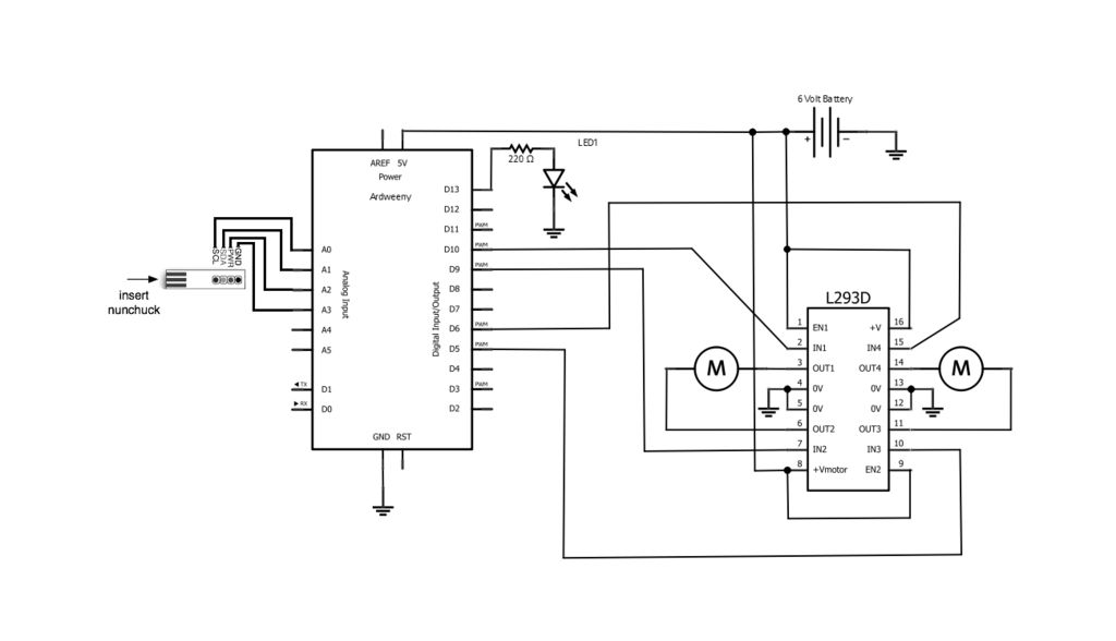
It uses one of my customized Ardweeny and an H bridge L293D motor driver chip:
– http://www.instructables.com/id/Ardweeny-2-How-to-customize-an-Ardweeny/
– http://www.freewebs.com/isuru-c/motor_driver.htm
My next step would be to make it wireless and add a couple of sensors; I was thinking of a tiny wireless camera too, however because it rolls so much it would not be very practical.
I hope you like this just as much as I did, I learned a couple of things along the way. I built this at the same time while working on two different robots and rovers, however this one was simpler in hardware requirement and the code, and I can see a lot of potential for learning off it and expanding from it. Also if you find it too tight to put all the components inside you can always just use the code and the hardware on a bigger customized frame.
Please let me know if something is not clear or you need more details.
Included is my code: Roll_A_Way_Rover_v1_1.pde
 Roll_A_Way_Rover_v1_1.pde
Step 1: Parts and Material used
1x Roll-A-Way Clock
1x Ardweeny 2 (http://www.instructables.com/id/Ardweeny-2-How-to-customize-an-Ardweeny/ )
1x USB interface for Ardweeny
1x H bridge L293D motor driver chip (http://www.freewebs.com/isuru-c/motor_driver.htm )
2x 16 DIP sockets (http://en.wikipedia.org/wiki/Dual_in-line_package )
1x small power switch
1x LED with small mounting clip
1x 220 ohm resistor
20x Short length Breadboard jumper wire – 4 inches – male to male
For the USB serial interface cable extension:
6x Medium length Breadboard jumper wire- 6 inches – male to female
2x Female Socket Strip – Strip of 6
1x Wii Nunchuck
1x Wii Nunchuck adapter (http://www.sparkfun.com/products/9281 )
6x Medium length Breadboard jumper wire- 6 inches – male to male
4x AAA batteries (rechargeable preferred)
Soldering equipment & basic tools.
Step 2: Taking apart the Roll A Way Clock
Remove the 4 screws at the bottom.
Once open, remove the LCD display assembly with the two push buttons attached to it, they will not be used *.
Remove the snooze button assembly and the four time settings buttons, keep the snooze plastic cover.
Remove the two motor and detach the wires.
Remove the speaker at the bottom.
Remove the battery box.
Warm up your soldering iron for the next steps.
* PS: there are instructions on how to use the clock LCD module with an Arduino and it is what got me started on this when I saw the gear motors inside and the price of the unit at a local store 😉
http://arduino.cc/forum/index.php/topic,51464.0.html
[box color=”#985D00″ bg=”#FFF8CB” font=”verdana” fontsize=”14 ” radius=”20 ” border=”#985D12″ float=”right” head=”Major Components in Project” headbg=”#FFEB70″ headcolor=”#985D00″]1x Roll-A-Way Clock
1x Ardweeny 2
1x USB interface for Ardweeny
1x H bridge L293D motor driver chip
2x 16 DIP sockets[/box]
For more detail: Roll-A-Way Rover using an Arduino