Steps
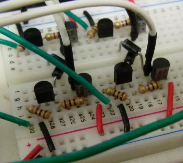
On the breadboard, build two bi-directional motor control circuits (also known as “H-bridge”) circuits. These circuits will control the two DC motors that drive the wheels. Each circuit will have two wires from the Arduino (one for forward, one for backward) to control the circuit, and two wires from the single DC motor that it is controlling.
You should test your circuits to ensure you can control both motors in both forward and reverse directions. Here is a sample Arduino sketch you can use to test the motors. Edit the code to check each motor and direction, and double-check the circuit for any motor that doesn’t behave as expected.
Now, the QRD1114 line sensors need to be mounted and wired to the Arduino.
Now test that both QRD1114’s are operating correctly, and sending a proper signal to the Arduino.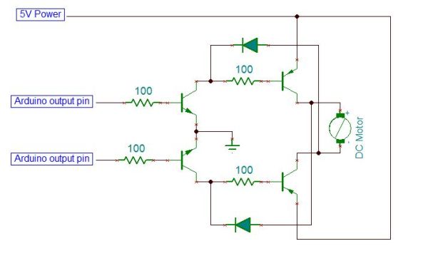 Here is a sample Arduino sketch to test the circuits. Make sure you are getting a good range of values from both sensors between light and dark. Make a not of the highest and lowest values you get from each sensor. You will use a value half way in between these for your “cut off” or “threshold” value. This is the boundary value we’ll use to decide if the sensor is seeing the dark line or not.
For more detail: Arduino MicroBot Project