Overview
This project builds a Christmas lights controller for the GE Color Effects lights allowing programmed control of up to 8 sets of Christmas lights. Furthermore, it provides a function specific language for programming patterns for these lights and an emulation environment for testing the programs requiring the lights to be built or hung.
Pre-reading
Arduino – If you have never heard of an Arduino, then I suggest you check out their site. They design and sell an open-source microprocessor platform which is great for building programmable electronic gadgets for those with limited electronics experience.
GE Color Effects – These have to be the coolest Christmas lights ever for the hacker. Each bulb contains a red, green and blue LED and can be controlled individually or as a group by sending instructions down a single data line. For a description of what they are and how they work, checkout this article which also provides basic control information that Robert Quattlebaum (darco) reverse engineered. While you are at it, do some Youtube searching for some very cool demos of what can be done with a microprocessor and a set of these lights (The ten string Christmas tree has to be seen to be believed).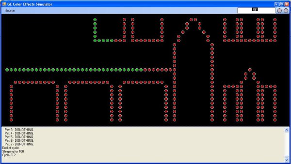
Introduction
This article is made up of a hardware project and 3 programs:
- The hardware project uses an Arduino Mega 2560 to control up to eight sets of lights.
- The first program is the firmware which runs on the Arduino Mega to control the lights. It does this by reading a set of instructions which are expressed in the form of an array of short integers for each string of lights which tell the firmware what patterns to generate with the lights. The firmware can also be cross compiled and run on the PC where they can do the same job but control a lights emulator. On the PC, I use the express version of VC++ to compile it.
- The second program is the lights emulator. This will emulate one or more sets of lights arranging them on screen according to your desired layout. When you run the firmware on the PC, this firmware will send the instructions to the emulator which will display the lights as they would appear. I use the express version of VC# to compile it.
- The final program is a compiler (or more correctly an assembler) which takes a higher level instruction set and generates the required array of short integers the firmware uses to tell it what to do with the lights. I use the express version of VC# to compile it.
This diagram gives you and idea of how everything works together …
To try this out, you don’t need an Arduino or to build any hardware … the compiler, the firmware (built for the PC) and the Emulator all run on your PC.
Hardware
I have significantly simplified the hardware design by removing the isolation circutry and going with a common ground configuration across multiple adapters. I was concerned about this causing problems but it seems to work ok.
In my first prototype, I used an Arduino Pro. It is cheap and works well but I quickly ran into memory issues as it only has 2K of RAM. Even with several refactorings to minimise memory use, I found I was running out of memory controlling 1 to 2 sets of lights. So I upgraded to the Arduino Mega 2560 with 8K of RAM. Still paltry but enough if you are very frugal with your memory use and you put all the static data such as the instructions into the more generous 256K of flash memory.
The Color Effects light comes with a 3A 5V adapter which is powerful enough to run 2 strings of lights. With 8 strings this requires 4 adapters and a 7.5V adapter to run the arduino. The circuit also includes some key elements which make it easy to use/test:
- A reset button which resets the program … as it does not cut power to the lights it does not reset any bulb addressing issues so sometimes you still need to cut the power
- 2 debug buttons. These can be held down on power up either singly or together to put to unit in one of 3 debug modes.
- A power LED that shows the arduino has power.
- An error LED that is used to flag errors and other conditions
- A progress LED which flashes as the program runs showing that all is good.
- Here is the full wiring diagram.
This is everything put together in a nice box. The Arduino is visible bottom left.
It is also worth making a few comments about the lights themselves. Each string of lights is 50 bulbs long. Bulb addresses are established during initialisation which using my firmware means they will be always numbered 0 … 49 in order from the controller to the end (but they don’t have to be). Each bulb can be individually controlled in terms of color and brightness. Brightness can also be controlled using a broadcast command to the mythical bulb 63. The bulb control protocol involves sending a pattern of low and high voltages down the data wire. Each high/low lasts for 10 microseconds and a full single bulb command takes 820 microseconds.
The Compiler
As mentioned above, the compiler is really more of an assembler as apart from some variable naming and jump measuring is basically substitutes some symbols for some numbers and emits a data file and a .h file for use in the firmware.
The instruction set is very simple and explained in detail in the TidlyWiki HTML file included in the download, so I will cover the basics here only.
The instructions are simple instructions relevant to a string of bulbs.
<span id="ArticleContent">// set bulbs 0..9 red and bright
SetColour
0
9
red
bright

// set bulbs 10 to yellow and 19 to blue and graduate bulbs 11..18
SetFadeColour
10
19
yellow
blue
bright

donothing
1</span>
Instructions are executed in cycles. All instructions are executed in the same cycle up until a donothing or a loop instruction is encountered.
Some instructions run across multiple cycles. These commands display an effect over multiple cycles such as gradually changing colour or brightness or even shifting bulbs around.
<span id="ArticleContent">// rotate bulbs 10..19 1 bulb to the right 50 times
RotateBulbs
10
19
1
50
1
1</span>
When controlling multiple strings of lights, you define a separate program for each string. When executing the cycle progression is centrally controlled, i.e., all strings complete their cycle 1 commands before the program proceeds to cycle 2. With careful authoring, you can then synchronise patterns across multiple strings of bulbs. Some of the pre-built examples included show how this is done. The secret is making sure you have the same number of cycles in each program.
The compiler emits a .dat file for each program. These files are used by the firmware when it is running on the PC allowing you to test programs without having to recompile the firmware for each test.
The compiler also emits a single .h file. This .h file contains up to 8 programs and is compiled into the firmware before deploying to the arudino. You only really need to do this at the very end when you are happy with how the program looks in the emulator.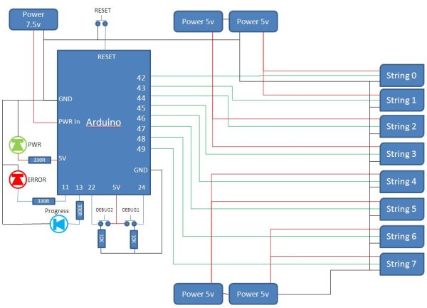 To compile, just pass in 1..8 program files to the compiler. The first passed is deemed program 0 in the .h file.
The compiler also understands some common concepts and has keywords to represent them to make programs more readable. Keywords such as NOCOLOR, LASTBULB, YES, NO. These are all covered in the TiddlyWiki file.
The Emulator
The emulator emulates up to eight sets of lights. It does this by displaying bulbs as small circles on the screen which it then colours according to the instructions received from the firmware when it is running on the PC. The firmware talks to the emulator by using a TCP/IP connection. The address used is kept in the tcpip.txt file. It is by default the loopback adapter 127.0.0.1 but can be another machine on the network.
The emulator can also get its input direct from an arduino connected over a Serial link. You can set this using the menu on the simulator and by including the appropriate #defines in the gloabl.h file. This slows down the program signficantly and should not be necessary except when trying to debug my firmware. When running in this mode you can even monitor the free memory on you ardunio.
The emulator can lay out the bulbs to represent how they might look when strung up on your house. To do this, just edit the house.xlsm file and generate an output.xml file which can replace the GELightsSimulator.xml file with your own layout.
For more detail: Simulating and controlling GE Color Effects Lights with Arduino