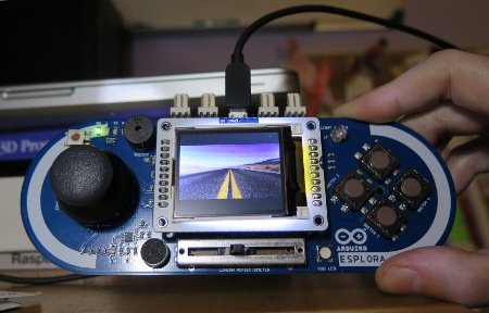
With this article I kick off my series on the Arduino Esplora board. Today’s project is a nice (and cheap!) little digital picture frame that uses the Esplora’s TFT Screen add-on.
Materials Needed
In this section you will find the materials that you need to obtain to build this project.
Arduino Esplora Board
The Arduino Esplora is the most feature rich of all the Arduino boards. It has the shape of a game controller, which makes it the coolest looking.
The Esplora board includes joystick, directional buttons, slider, RGB LED, temperature sensor. microphone, buzzer and accelerometer, all on-board, so it can work for lots of different projects. A screen is sold separately.
The official price for this board is currently $59.99 USD. The Chinese electronics stores on Ebay sell clones for much less, but you’ll have to wait several weeks for it to arrive.
Links: Amazon,
TFT Screen
The second component that you need is the Arduino TFT screen. This is a small 160×128 pixel 16-bit color display that plugs into a socket on the Esplora board. This screen also includes a micro-SD card slot that will give the Arduino board the ability to read and write files to SD cards.
The original Arduino brand of this screen costs $25, but it has been out of stock for a while. There are many clones on Amazon and Ebay that sell for the same or lower price.
Links: Amazon,
Note: when you buy the screen make sure it is the kind that plugs into the Arduino Esplora, as there are other very similar screens that have different connectors.
Power Cable
To power the Arduino Esplora you need a mini-USB cable, the kind that many smartphones use these days to charge:
Hardware Setup
The hardware preparations are really simple. The TFT screen plugs into the front socket of the Arduino Esplora. After you connect it you can power the board by connecting it to your computer using the USB cable.
If you are using a Windows PC you need to install drivers for your Arduino board. The process is explained in the Arduino documentation. If you are using Windows 8 there is an additional complication because the Arduino drivers aren’t signed by Microsoft and this version of Windows does not accept drivers that are not signed. The process to bypass the signed driver requirement is described in detail in this page.
Users of Linux and Mac OS X do not need to install any drivers.
 Software Installation
Now it is time to install the Arduino Software. This software contains the tools to write and upload programs to your Arduino board. Make sure you install version 1.0.5 or newer.
With the Arduino board connected, launch the Arduino software. In the Tools menu open the Board submenu and make sure you select the Arduino Esplora from the list.
Then in the Port submenu you have to select the serial port entry that corresponds to your board. On Windows this is going to be something like COM<n>, on Mac OS X /dev/tty.usbmodem<nnn> and on Linux /dev/ttyACM<n>.
A First Arduino Program
The large white area in the Arduino software is where programs are entered. Type (or copy/paste) the following C++ program there:
void setup()
{
    Serial.begin(9600);
    pinMode(13, OUTPUT);
}

void loop()
{
    Serial.println("Hello, world!");
    digitalWrite(13, HIGH);
    delay(500);
    digitalWrite(13, LOW);
    delay(500);
}
The setup() and loop() blocks are called functions. These two functions are present in all Arduino programs.
The setup() function contains instructions that initialize the Arduino. In the above example the serial port is initialized to run at 9600 bauds, and pin 13 is initialized as an output pin.
The loop() function contains the body of the program. This function is called over and over. In the example the function prints the message “Hello, world!” to the serial port, then gives power to pin 13, which on most Arduino boards turns an on-board LED on. The delay() function waits for the number of milliseconds given as argument, in this case half a second. After the delay the LED is turned off by removing power from pin 13, and then another wait of half a second is done. The cycle then repeats.
To upload and execute this program in your Esplora board press the “Upload” button in the toolbar (second button from the left).
The text written to the serial port is sent over the USB cable to your computer. You can view it by opening the Serial Monitor, the button at the far right of the toolbar. If you don’t see the greeting printing once per second then make sure the baud selection in the Serial Monitor is set to 9600 to match the program.
Controlling the Screen
The TFT screen is controlled with the help of the TFT and SPI libraries that come with the Arduino software. Libraries contain utility functions that are generic and can be used by many programs.
The following Arduino program makes the screen alternate colors between black and white:
#include <TFT.h>
#include <SPI.h>

bool black = false;

void setup()
{
    EsploraTFT.begin();
}

void loop()
{
    if (black) {
        EsploraTFT.background(255, 255, 255);
        black = false;
    }
    else {
        EsploraTFT.background(0, 0, 0);
        black = true;
    }
    delay(1000);
}
The #include statements at the start of the program import the two libraries that are required to control the screen.
The EsploraTFT object represents the screen. In the setup() function its begin() method is invoked to initialize the display. Then in loop() the background() method is called to change the color. The three arguments to background() are the red, green, blue components of the color, each a value from 0 to 255. The black variable declared near the top is used to alternate the colors each time loop() executes.
For this project images will be displayed on the screen. To have the most flexibility I have decided to write my own image drawing function, so the individual pixels need to be set one by one to the correct color, using the drawPixel() method. As an introductory example to pixel drawing, the following Arduino program draws a horizontal red line in the middle of the screen:
#include <TFT.h>
#include <SPI.h>

void setup()
{
    EsploraTFT.begin();
    EsploraTFT.background(0, 0, 0);
}

void loop()
{
    int width = EsploraTFT.width();
    int height = EsploraTFT.height();

    int row = height / 2;

    for (int col = 0; col < width; col++)
        EsploraTFT.drawPixel(col, row, 0x00F8);
}
This program sets the background color of the screen in the setup() function. In loop() it obtains the dimensions of the screen in pixels and then uses a for-loop to draw the line of pixels.
The drawPixel() method takes three arguments. The first two are the column and row for the pixel to draw. The third argument is the color, which for this method is not given as three numbers for red, green and blue. Instead, the color is given as a single number in the internal 16-bit representation of the screen. The red and blue channels use 5 bits each, while the green channel uses 6 bits. The representation is as follows:

0000 0000 1111 1000, or 0x00F8 in hexadecimal. A 50% red color would be 0000 0000 1000 0000, or 0x0080.
If this seems like an arbitrary representation consider that the Arduino has a little-endian CPU, so the two bytes are reversed when stored in memory. And now the five red bits appear first, followed by the six green bits and then the five blue bits.
Image Processing with Python
If you search for other picture slideshows for the Arduino you will find that most, if not all, read the images in BMP format from a memory card installed in the SD slot in the back of the LCD screen. This requires you to convert the images, which you probably have as high resolution JPGs to 160×128 BMPs.
For this project I’ve decided to take a completely different approach. Instead of using the SD card as storage I take advantage of the serial connection between the Arduino and the computer. The Esplora acts as a server, it waits for the computer to send pictures to display over the serial port.
The following Python script runs on the computer connected to the Arduino and accomplishes the task of loading an image, scaling it to 160×128 while preserving the aspect ratio and finally sending it one pixel at a time over the serial port:
from serial import Serial
from PIL import Image

def upload_image(filename, screen_size, serial):
    img = Image.open(filename)
    img.thumbnail(screen_size, Image.ANTIALIAS)
    img_data = img.getdata()

    # center image on display
    top_margin = (screen_size[1] - img.size[1]) / 2
    bottom_margin = screen_size[1] - img.size[1] - top_margin
    left_margin = (screen_size[0] - img.size[0]) / 2
    right_margin = screen_size[0] - img.size[0] - left_margin

    # send image data over serial port
    serial.write('I')
    for row in range(top_margin):
        for col in range(screen_size[0]):
            serial.write('\x00\x00')
    i = 0
    for row in range(img.size[1]):
        for col in range(left_margin):
            serial.write('\x00\x00')
        for col in range(img.size[0]):
            red = img_data[i][0] >> 3
            green = img_data[i][1] >> 2
            blue = img_data[i][2] >> 3
            serial.write('%c%c' % ((((green & 0x03) << 5) | red), (blue << 3) | (green >> 3)))
            i = i + 1
        for col in range(left_margin):
            serial.write('\x00\x00')
    for row in range(bottom_margin):
        for col in range(screen_size[0]):
            serial.write('\x00\x00')

serial = Serial('/dev/ttyACM0') # <--- enter your own serial port here
upload_image('santi.jpg', (160, 128), serial) # <--- enter a path to a jpg image here
To run this program you need a Python interpreter and the pyserial and pillow packages. If you have pip installed on your system then you can install these packages as follows:
$ pip install pyserial pillowSome Python distributions come with easy_install instead:
$ easy_install pyserial pillowThe upload_image function opens the image file given as the first argument and scales it down to the dimensions of the screen, given as a second argument. This is all done using the Image class from pillow. The img_data variable holds an array of pixels for the resized image, which each pixel represented by a 3-element tuple.
The resized image may not fit exactly in the screen due to its aspect ratio, so the function then computes the margins to center the image.
Finally, the function converts each pixel to the 16-bit format used by the Arduino TFT screen and sends each as two bytes over the serial connection, given as third argument to the function.
The character I is sent before the image data, to inform the Esplora that an image is coming. It is always a good idea to leave room for expansion in any communication protocol, so by adding a one byte prefix new commands can be added later.
The data sent over the serial port matches exactly the size of the screen, so the margins that were calculated before are used to generate black pixels that complete the picture.
Copy/paste the script above and write it as file upload_img.py, as you will be able to use it soon.
Receiving and Displaying Images
The Arduino program that receives and displays images sent by the Python script is shown below:
#include <TFT.h>
#include <SPI.h>

unsigned short *line = 0;

void setup()
{
    EsploraTFT.begin();
    EsploraTFT.background(0,0,0);
    Serial.begin(115200);
    line = new unsigned short[EsploraTFT.width()];
}

void loop() {
    if (Serial.available() > 0) {
        char cmd = Serial.read();
        switch (cmd) {
        case 'I': // image
           for (int row = 0; row < EsploraTFT.height(); row++) {
                bytes = EsploraTFT.width() * 2;
                char* p = (char*)line;
                while (bytes > 0) {
                    int n = Serial.readBytes(p, bytes);
                    if (n == 0) {
                        // timeout
                        return;
                    }
                    p += n;
                    bytes -= n;
                }
                for (int col = 0; col < EsploraTFT.width(); col++)
                    EsploraTFT.drawPixel(col, row, line[col]);
            }
        }
    }
}
This program initializes the screen with black background and sets the speed of the serial port at the maximum, which is 115200 bps. A buffer that is big enough to hold an entire line is also allocated during initialization.
In loop() the program waits until the is serial data available, and then reads one byte. If it is the I byte then it gets into a for-loop that iterates over all the rows in the image. For each row it reads the entire line of 16-bit pixels into a buffer. Once the entire line is stored an inner loop that iterates on the columns draws the pixels using drawPixel().
Why read all the pixels in a row before drawing them? Because it is more efficient to issue large reads. Reading pixels one by one and drawing them is slower because the cost of issuing a read does not scale directly to the size of the read, each read has a fixed cost associated with it, so the least amount of reads the more efficient the program will be.
Why read a line using a while loop? Because the serial port in the Arduino has a buffer of only 64 bytes, so a single read would never return more than that amount. An entire line has 160 pixels, which at 2 bytes per pixel make it a 320 byte buffer.
 Copy/paste the above program into the Arduino software and upload it to your Esplora. Once the screen turns black the board is waiting for images sent from the computer.
Now you can run the Python script to send an image over, but first make sure you edit the bottom two lines to use the correct serial port number for your board and the path to a JPG image that you want to use:
$ python upload_img.pyAnd voila! You should now be seeing the image displayed on the Esplora screen.
Some Improvements
I have a more robust version of the code presented above in a GitHub project:
The Arduino side is called server.ino, and has been expanded to also support other Arduino boards besides the Esplora.
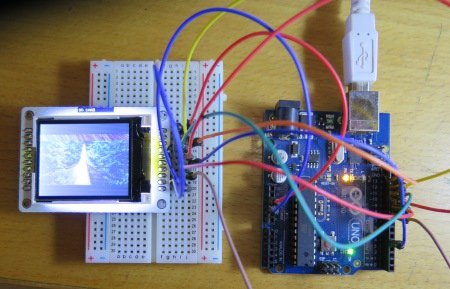
If you connect the LCD screen to a different Arduino then you can run this program by removing the IS_ESPLORA definition at the top and setting the correct pin constants where the TFT object is initialized.
If you recall, images are prepended with an I character in the serial communication. This version of the Arduino program accepts a second command, prefixed with the letter C for “connect”. When the client sends this command the Arduino responds by writing the width and height of the screen to the serial port. This is useful to make the client software independent of the hardware. If one day you install a larger screen then the client will not need to change, since the picture dimensions are discovered from the communication with the device.
The Python script, called client.py is given a folder in the command line arguments. During start up the script searches the folder and all its sub-folders for jpeg pictures. Random images found in this folder are uploaded periodically to the Arduino board, making it into a slideshow.
The supported command line arguments are shown below:
$ ./client.py  --help
usage: client.py [-h] --port PORT [--folder FOLDER] [--interval INTERVAL]

Send pictures to the Arduino based digital picture frame.

optional arguments:
  -h, --help            show this help message and exit
  --port PORT, -P PORT  serial port number, starting from zero.
  --folder FOLDER, -f FOLDER
                        picture folder (default: current directory).
  --interval INTERVAL, -i INTERVAL
                        interval between pictures (default: 10 seconds).
  --baudrate BPS, -b BPS
                        serial port baud rate (default: 115200 seconds).
Below is a screenshot of the TFT screen connected to an Arduino Uno.
For more detail: Fun With The Arduino Esplora: A Digital Picture Frame