For years I have been telling anyone who listens that I was going to build a robotic drum. Most people kind of shrugged indifferently. Even as I built it, most people kind of glanced over at it and conveyed doubtfulness. It seemed like no one but myself was convinced of just how awesome it was going to be.
I received a lot of snarky comments about how I was making a strange annoying noise maker. When I finally go it set up for the trial run, I quickly silenced the naysayers. This robotic drum blew everyone away. I was finally able to convey my vision and explain why someone would ever want to build a robotic drum.
The reason to build a robotic drum is because it is plain super-awesome. It keeps a beat like clockwork. You can slow down and speed up any drum beat with precision and ease. It can even play things a real human drummer could never do.
I intend to use mine for rocking out. The current plan is to program it with different drum beats and play guitar along with it.
I decided to use linear actuators (car door lock motors to be exact), and Arduinos with motor controller shields simply for ease of use and duplication. I am sure there are other more elegant ways to interface with the motors, but this is by far the easiest.
Step 1: Go get stuff
You will need:
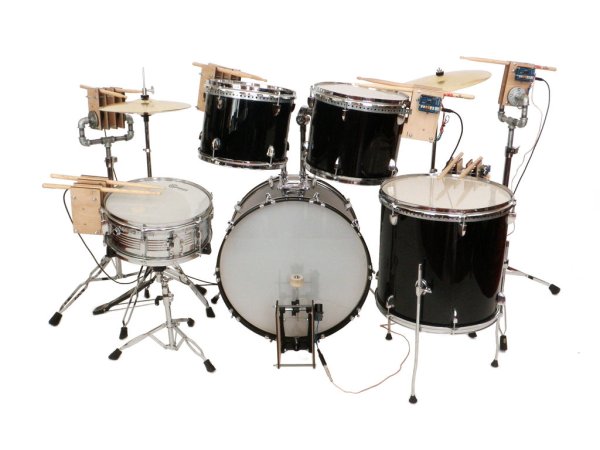
(x1) Drum set (Amazon)
(x12) Drum sticks (Amazon)
(x12) Car door lock actuator motor (Amazon)
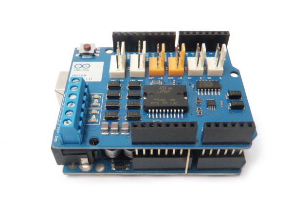
(x6) Arduino Uno (Radioshack #276-128)
(x6) Arduino Motor Shield (Radioshack #276-131)
(x1) 7″ x 5″ x 3″ project enclosure (Radioshack #270-1807)
(x1) European-style terminal strip (Radioshack #274-680)
(x2) 24′ spool 18 AWG speaker wire (Radioshack #42-2456)
(x3) Panel mount M-type power socket (Radioshack #274-1563)
(x1) 1/4″ mono jack (Radioshack #274-252)
(x1) 1/4″ mono plug (Radioshack #274-1536)
(x1) 4″ zip tie (Radioshack #278-1632)
(x1) Stranded 22 AWG red and black wire spools (Radioshack #278-1224)
(x1) Assorted shrink tube (Radioshack #278-1611)
(x3) 9V 1.5A power adapters (M-type plugs) (Radioshack #273-356)
(x1) Power strip (Radioshack #61-056)
(x1) 7 socket USB hub (Radioshack #55053562)
(x6) 6′ USB A to B cable (Radioshack #55010623)
(x1) 4′ x 8′ x 1/4″ plywood sheet
(x4) 1/2″ pipe mounting flange
(x1) 24″ x 1/2″ threaded pipe
(x1) 18″ x 1/2″ threaded pipe
(x8) 1/2″ pipe L-bracket
(x2) 1/2″ pipe T-bracket
(x2) 1″ threaded pipe
(x4) 2″ threaded pipe
(x4) 2-1/2″ threaded pipe
(x2) 3″ threaded pipe
(x2) Cymbal stands
(x3) 3/4″ x 10′ 22 gauge steel hanger strap
(x16) 8 – 1/2″ wood screws
(x20) 1/4 x 5″ bolts
(x4) 1/4 x 2″ bolts
(x1) Box of 1/4 nuts
(x22) 6-32 x 2″ nuts and bolts
(x4) 6-32 x 1″ nuts and bolts
(x11) 1-1/2″ binding posts
(x20) 1-1/2″ (1/4″ i.d.) spacers
(x18) 4-40 x 1-1.2″ nuts and bolts
(x18) 1/4″ (1/8″ i.d.) spacers
You will also need to download the attached files and laser cut (or cut the old fashioned way) the following:
(x16) Drum brackets
(x6) Cymbal brackets
(x4) Cymbal bracket circle spacers
(x2) Kick drum brackets
Step 2: Attach the motor
Step 3: Make another
Once the bolts are passed through, make another motor bracket “sandwich” like you did in the last step.
Step 4: Motor pair
Repeat for all of the other holes.
Thread a nut all the way down one of the bolts to hold it in place, and then repeat for all of the other bolts
Slide a spacer over each of the bolts and then thread more nuts on to hold them all in place.
Slide the other motor bracket “sandwich” onto the bolt.
Fasten everything securely in place with another nut.
Step 5: Drill a hole
Make a mark at 5-1/8″ and 7-1/4″.
Drill down through all of these marks with a 3/16″ drill bit, to leave an identical pair of holes in each stick
Repeat this process 5 more times, to make 6 sets of drilled drum sticks.
Step 6: Attach drum sticks
Pass a binding post from the outside of the assembly through the corner pivot hole, through the hole in the drumstick closer to the tip, and then through the inner pivot hole.
Fasten the binding post shut.
Zip tie the drum sticks to the motor assembly using the other drilled hole.
Repeat this process for the other motor.
Step 7: Build more
Step 8: Glue and clamp
To attach this wood piece, simply lay down a little bit of wood glue, align the pre-drilled 1/8″ pilot holes, and then once aligned, clamp them in place.
Don’t forget to make certain that one of the pieces you are gluing the wood piece to has holes for mounting the Arduino.
Step 9: Motor brackets
Step 10: Assemble
Step 11: Build the mount
Connect L-brackets to each end of the respective threaded pipes.
Thread a 2″ section of threaded pipe onto the end of each L-bracket.
Again, put L-brackets on the end of each respective threaded pipe.
Thread a 1″ section of threaded pipe onto the end of each L-bracket.
Finally, attach flanges to the end of each threaded pipe.
Step 12: Attach
Rotate the flanges as necessary so that the pilot holes are aligned with the flange’s mounting holes.
Fasten the drumstick assembly to the mounting bracket place with wood screws.
Step 13: 18″ pipe
Step 14: Connect drum sticks
Again, zip tie the drum sticks to the linear motor assembly.
Step 15: Clamp and glue again
Make sure that when you do this, the extra piece of wood will be on the outside when you make your motor “sandwich.”
Simply lay down a little bit of wood glue, align the pre-drilled 1/8″ pilot holes, and then once aligned, clamp them in place.
Step 16: Assemble
Assemble it accordingly, with the extra bits of wood facing out.
Don’t forget to install the Arduino mounting screws as well.
Step 17: Build another mount
Connect L-brackets to each end of the respective threaded pipes.
Thread a 2-1/2″ section of threaded pipe onto the end of each L-bracket.
Again, put L-brackets on the end of each respective threaded pipe.
Thread a 2″ section of threaded pipe onto the end of each L-bracket.
Finally, attach flanges to the end of each threaded pipe.
Step 18: Fasten
Step 19: 24″ pipe
Step 20: Connect the drum stick
Step 21: Prepare the kick drum pedal
Remove the spring that is keeping tension on the pedal’s rotational assembly.
Using the mounting holes in the wooden bracket as a guide, drill 1/4″ holes on both sides of the pedal. This should result in 2 holes on each side of the pedal.
Step 22: Attach
Step 23: Spacers
Insert 5″ x 1/4 bolts through the bracket’s structural mounting holes, using the pens as spacers in-between the two.
Fasten each bolt firmly in place with a nut.
Step 24: Attach motor
Attach the motor to the wooden bracket using 6-32 nuts and bolts.
Zip tie the motor shaft to the rotational pivot of the kick drum pedal.
Step 25: Socket
If the motor does not have red or black wires, designate one of the colors to be ground and the other to be power. In this case, the green wire will be ground.
Step 26: Jack
Take apart the 1/4″ plug, and go grab about 5′ of speaker wire.
Solder the marked edge of the speaker wire to the ground terminal.
Solder the unmarked edge to the tip terminal.
Reassemble the plug when you are done.
For more detail: Arduino-Controlled Robotic Drum